
I just got a good deal on several PIC18F4550 chips. So, I decided to make a Do-It-Yourself Pinguino PIC18F4550 Board to test them out. The Pinguino boards are based on the same concept as an Arduino. However, instead of Atmel chips, Microchip PIC® chips are used. All of the Pinguino boards use PIC® chips with on board USB, so the boards are quite easy to access/program. The goal of the Pinguino project is to bring the simplicity of Arduino language to the Microchip PIC® microcontrollers with built-in USB hardware. (Visit the Pinguino project WEB site here.)
The IDE for the Pinguino boards is similar to the Arduino IDE and sketches are also similar, so Arduino users should feel right at home. Pinguino Hardware and Software, like the Arduino, is all Open Source.
Here is a schematic, a breadboard layout and the DIY Pinguino circuit board I created using the PIC18F4550 microcontroller chip:
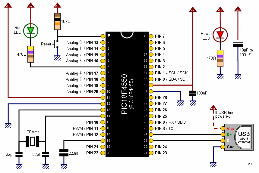
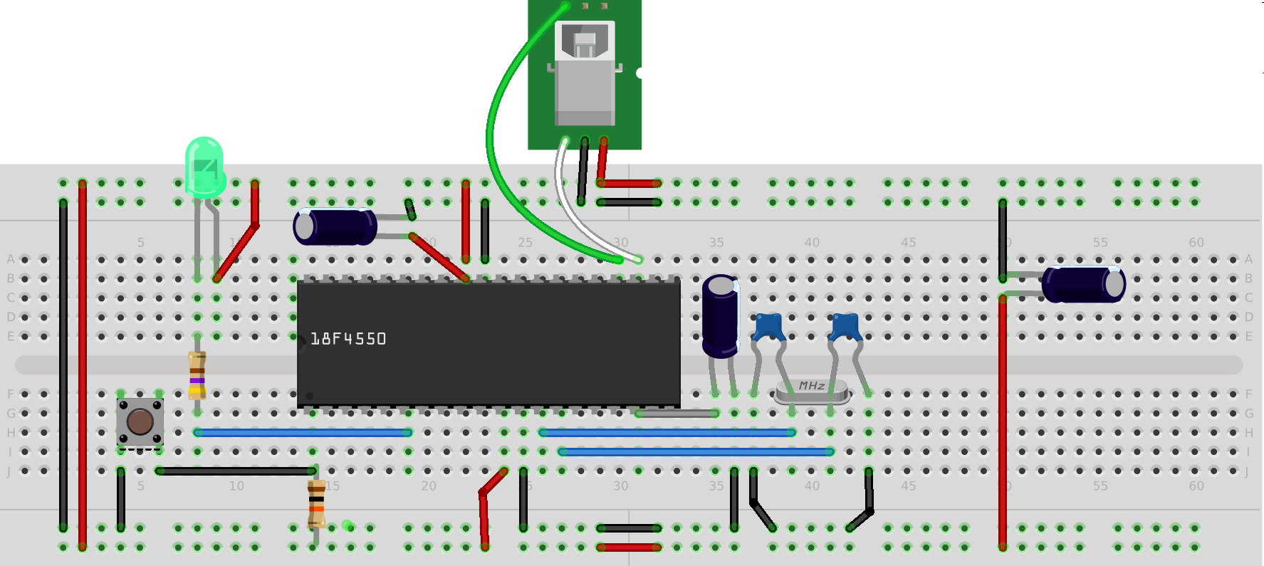

Do-It-Yourself Pinguino PIC18F4550 Board
You might notice that in the circuit I built (although not shown in the schematic), I added a 6-pin ICSP header so I could initially load the bootloader by attaching a PICkit 3 programmer:

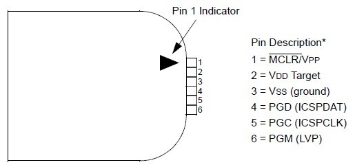
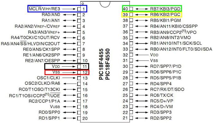
The PICkit 3 plugs nicely into the 6 pin header. The graphic above shows how the ICSP pins of both the PICkit and PIC18F4550 are connected. The bootloader (Version 4) I used can be downloaded here.
Here are the top and back views of the board:

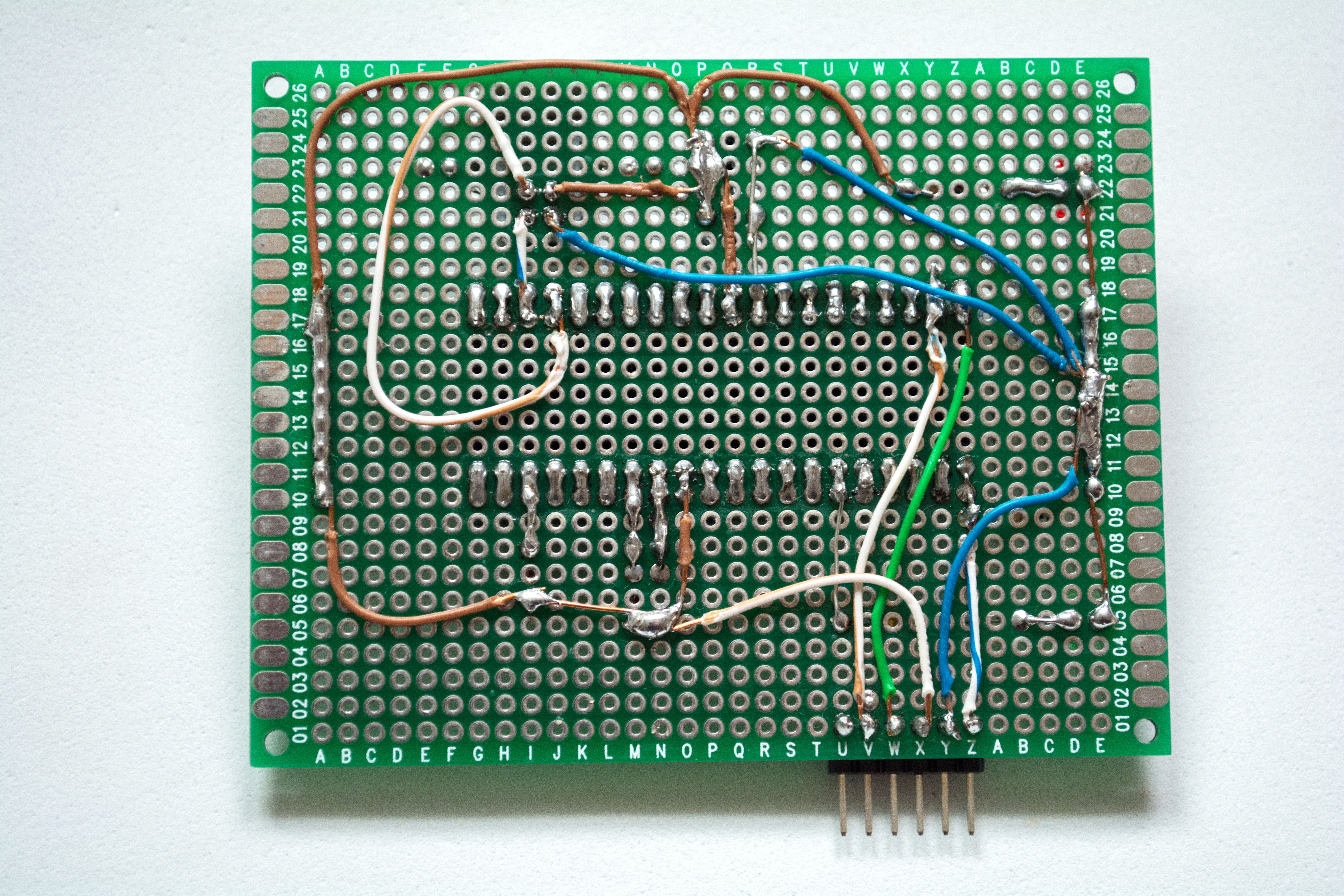
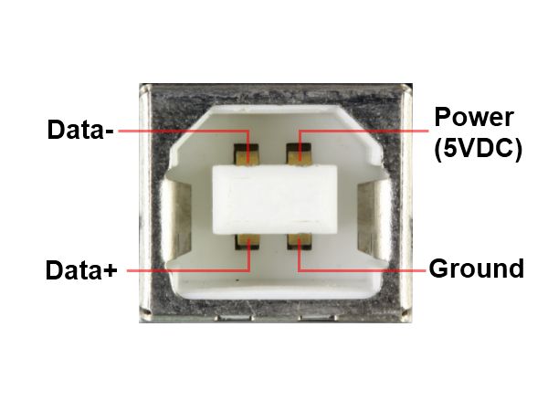
I soldered on four 10-pin female headers so that connections can be easily made to any pin. I also plugged in two 10-pin male-male headers (un-plugable) so that I can use any jumper wire that I may have around. The male header PINs between the LEDs are all wired to +5V and the male header PINs at the other end of the board are all wired to GND so there is easy and ample connection to either. I used a type B female USB connector (so it fit the USB printer cables I have so many of).

If you’d like the Fritzing diagram for this board you can download it here or the original SVG graphic here. For more information about the Pinguino project visit their Wiki.
3 comments
may I ask for the data on the pic184550 as fritzing part
Author
The end of the post has links for both the fritzing diagram and the SVG graphics. However, if you missed that here is the link: Pinguino 18F4550 Fritzing Diagram
You can load that into the Fritzing software and extract the 18F4550 part (which is just a generic IC re-labeled as a PIC 18F4550).
The pinguino site is down.. more info here:
https://github.com/PinguinoIDE/pinguino-ide/issues/115