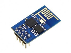
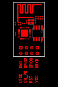
My children bought a present for me recently (yes, another birthday, I really am getting older 🙁 ). It is an ESP8266 Module which is a self-contained [IoT] Wi-Fi networking solution. Here are pictures (with the pins labelled):
My module comes from Elecrow.com. Since this module is rather new there is not much documentation nor sample code for it, however there is a WEB site dedicated to these devices here : esp8266.com.
The SDK is here. The Cross-Compiler is here. A very handy ESP8266 ROM Bootloader utility is here.
The module I have takes 5 pins (3.3V, GND, TxD, RxD and CH_PD). The CH_PD pin on my module needs 3.3V. The default BAUD rate for my module is 115200. I connected to it using an FTDI cable and Minicom. (For 3.3V I used an Arduino Nano.)
Here is a good article on hooking it up similar to how I did it with links to new firmware, sample code, newer SDK and other tools.
I plan on eventually attaching mine to an Arduino and using it to send sensor data to a WEB site for data collection.
Since the ESP8266 is a serial device and the debugging ‘view’ to what is going on with it (USB to the Arduino) is also using a serial connection (FTDI probably), two serial connections are needed. I probably should explain this (especially if you are new to using Arduinos). All Arduino boards have at least one serial port (also known as a UART or USART). The serial port communicates using digital pins 0 (RX) and 1 (TX) as well as communicating with the computer via USB. So, if you use USB to communicate with the Arduino, you cannot also use pins 0 and 1 for digital input or output and thus you need to another serial port to both communicate with the Arduino and the ESP8266.
One might be tempted to try the Arduino software serial library to connect to the ESP8266, however the software serial library is too slow to keep up. Two hardware serial connections are therefore needed. An Arduino Leonardo, Due or Mega 2560 have at least two hardware serial interfaces and would work fine for this purpose.


Recent Comments