Coding for the Raspberry Pi Pico on Fedora or a Raspberry Pi

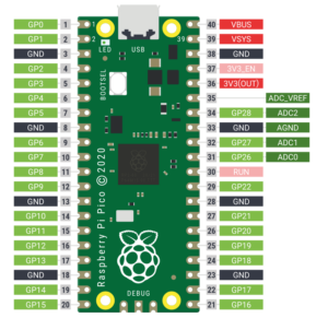
Back in January of this year (2021), the Raspberry Pi Foundation came out with their first microcontroller board calling it the Raspberry Pi Pico.

Raspberry Pi Pico Pinout Diagram

Raspberry Pi Pico Pinout Diagram

The microcontroller chip (RP2040) used on the Pico was designed by the Raspberry Pi foundation and features a dual-core Arm Cortex-M0+ processor with 264KB internal RAM, support for up to 16MB of off-chip Flash and a wide range of flexible I/O options which includes I2C, SPI, and Programmable I/O (PIO). The PIO is something unique in the microcontroller world. The RP2040 was also made available to other microcontroller board manufacturers so we are now seeing boards from Adafruit, Arduino, Sparkfun and others. It will be interesting to see how this chip is used in the future, especially in regards to the programmable I/O (PIO).

Coding (i.e. setting up a development environment) for the Raspberry Pi Pico on a Raspberry Pi is made easy by all the great documentation that is available from the Raspberry Pi Foundation.

Although, the documentation is designed specifically for using a Raspberry Pi and the Rasbian OS, you might find other similar Linux distros mentioned in the documentation (like Debian).  There is a pico-setup script provided but it is only useful on Rasbian.

Programmers have their choice of Python (using MicroPython or CircuitPython), C/C++ (using the SDK) or native assembler (using pioasm). If you are developing in C/C++,  I highly recommend the Pico Project Generator tool for creating new projects.

I happen to like and use the Fedora Linux distro (Fedora 34 at the time of this post). Fedora is a lot different than Raspbian and  some of the software dependencies needed for pico development and debugging are not documented. Actually, some of the pico tools do not compile correctly on Fedora without some modifications. Fedora tends to be on the leading edge and has more recent software development ‘toolchain‘ packages.

There were two specific things I found that did not work on Fedora without modification.  OpenOCD and PicoTool (both documented in the Getting Started Guide) compiled and worked OK on Raspbian but did not compile under Fedora.

To resolve these issues and make something to easily install ‘everything’, I  created a Python script (and other shell based scripts) to download and install the software development kit (SDK),  tools,  documentation and software dependencies for either Fedora or Raspian.  All of these scripts work on either OS.  When installing on Fedora, the scripts make the necessary modifications to compile OpenOCD and PicoTool correctly.

Download the pico-setup.zip file and unzip it to a directory of your choice. Something like:

mkdir /opt/pico
cd /opt/pico
wget https://microcontrollerelectronics.com/sourcecode/pico-setup.zip
unzip pico-setup.zip

The python script (pico-setup.py) and all of the provided shell scripts are  designed to run either on a RedHat (Fedora) system or a Raspberry Pi with Raspbian. The scripts (if necessary) determine which OS is being used at runtime.

Pico-setup.py accepts from one to three parameters (Toolchain, Install, Remove).
The ‘toolchain‘ parameter installs (via APT or DNF depending on the OS) the necessary prerequisite packages for these scripts to work on the underlying OS.  The ‘install’ parameter runs all the provided shells scripts. However, the  shell scripts can be run independently and thus only the ones specifically desired (although some depend on the SDK being installed first and they also depend on the OS toolchain dependencies being installed). The provided README.txt  file provides more documentation on its usage.


Connecting a serial port to the WEB via Node.js

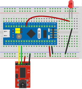
A previous post (here) documented how to connect a Python script to a serial port on a microcontroller.  This post documents connecting a serial port to the WEB via Node.js (which is a JavaScript runtime).

Using Node.js and a module for node called serialport, it is very easy to connect a PC to a serial port on a microcontroller.   First install Node.js  (and npm which is the node package manager). Then install the serial port package via:

npm install serialport

NODE.JS to Console Javascript code

Save the following code as serial_port_console.js:

and run it via:

node serial_port_console.js

This is a very simple means to communicate with your serial device just from the console. Data received from the serial device is sent to the console and data typed in on the console is sent to the serial device. Note that the serial port on the PC is hard coded as “/dev/ttyUSB0” and the baud rate is 115200 which should be changed by editing the code to match the connected device.

NODE.JS to WEB Javascript code

Alternatively, use this script for connecting a serial port to the WEB via Node.js:

That script also requires an html file to send to the browser:

Save the Node.Js file as serial_port_web.js and the  html  file as index.html. This script also requires three other npm modules (fs for reading files,  express for the WEB interface and socket.io to maintain a WEB socket connection for the serial data flow).

Install them with:  npm install socket.io fs express

Make sure the microcontroller serial device is connected to the PC, then run the script via:

node serial_port_web.js

The serial_port_web.js script will search for the serial port and use what is found  at a baud rate of 115200 unless it is over ridden with optional parameters on the command line:

node serial_port_web.js  /dev/ttyUSB0 9600

The port is hard coded to 8888 but of course can be changed by editing the code.

When the script is running ,  copy/paste this URL in the browser:

http://localhost:8888

and this screen should appear:

Serial Port to WEB via Node.JsThe large top blue box is where the serial data will be displayed (and a time stamp added). The bottom blue box is where data can be typed to send to the serial device. Note that when Enter is pressed, Enter (or as it is called the Carriage Return or Newline character) is sent to the serial device.  Pressing the Send button (sends the typed in characters without sending Enter.) Depending on what (code) is running on the serial device, sometimes the Enter is needed and sometimes not.

There is a lot more code in the WEB example, than in the console example, however, the WEB example has more features and presents the data in a ‘prettier’ way. Using the WEB example also allows a remote connection to the serial device if the host computer is connected to the internet.

An STM32F103C8T6 based MIDI Controller for MIDI2LR (Updated)

In a previous post (here) ,  a project was introduced for those of you who use Adobe Lightroom. There is a way to use a MIDI hardware ‘box’ to control various Lightroom actions. I am told that once you use the hardware controls you will never want to go back to the software ones.  A Lightroom plugin called MIDI2LR  interfaces various MIDI ‘boxes’ to  Lightroom. The MIDI box sends MIDI Control/Change commands to MIDI2LR which then changes them into Lightroom actions. More info on MID2LR can be found HERE.

This post continues the project by adding multiple rotary encoders (in addition to the buttons). Here is how things are wired (download the Fritzing.org file for this graphic here):

Here is how it  actually looks all wired together:

In this project (so far) there are two STM32F103C8 microcontrollers. One contains the MIDI control code and interfaces via USB to the PC. It also controls the OLED screen and buttons.  Another one controls the five rotary encoders. A previous post (here) documents the STM32F103C8T6 and interfacing with rotary encoders.

Also shown in the picture above are how the STM32F103C8 microcontrollers are programmed. The one on the left has an FTDI serial-to-usb connector and the one on the right has an ST-Link programmer connected.

The two STM32F103C8 microcontrollers are connected together via I2C (two wires).  To add more rotary encoders, just add another STM32F103C8T6 and up to  five encoders.

In the above picture, at the top left, is a simple I2C circuit which was introduced in a previous post here. Using that circuit, multiple groups of rotary encoders can be added (each additional STM32F103C8T6 can control up to 5 more encoders).

Here is the code (using the Arduino IDE) to load into the STM32F103C8T6 controlling the USB connection, buttons and OLED:

Note: The above code is an enhanced version from the previous post (here) were this project was only using buttons.

Here is the code to load into the STM32F103C8T6 which controls the rotary encoders:

Note: those two sketches will need to be updated if more encoders are added.

Once the code is sent/loaded into the two microcontrollers, just plug in the USB-micro cable (shown in the picture on the right) to your Windows 10 PC and it will be added as an audio device (no drivers are needed as it is automatically recognized). Install the MIDI2LR plugin and while in Lightroom you can test out the button and rotary encoder functions and customize the functionality.

Next up for this project is a custom case,  cleaning up the wiring and adding more encoders! Stay tuned!

Multiple Rotary Encoders on an STM32F103C8T6

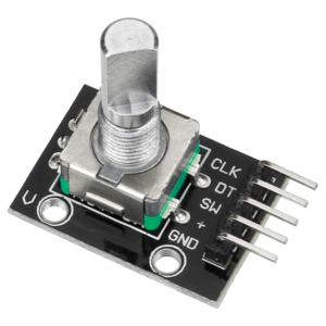
Rotary encoders are useful for many things.  Here is what they look like (with and without the button):

Rotary EncoderRotary Encoder with Button

They have 5 connections (Power, Ground, Data, Clock and Switch). The button can be turned (continuously in any direction) and it can also be pushed down .


The switch connection monitors the button push whereas the data and clock connections are used to monitor the direction and turn of the button.  There are many tutorials on how these ‘encoders’ work, for more information check this link.

Multiple encoders are needed for the MIDI2LR  project that was posted here. In order to test multiple encoders , this sketch called ‘Multiple Rotary Encoders on an STM32F103C8T6’ was created:

The pins are set up in an array so that the code can quickly ‘scan’ through them and not miss any state changes.

Notice that the switch (button press) pins are set up as INPUT_PULLUP.  If they go ‘LOW’ then the button was pushed.

Here is what the wiring looks like:

STM32F103C8T6 Multiple Rotary Encoders

Get the fritzing.org code for that wiring graphic here (so it can be modified if needed).

Powering your electronics projects with an ATX power supply

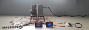
Working with different electronics projects,  and especially microcontrollers , requires different voltages (usually 3.3,  5 and 12 Volts).  It is very fitting that the power supply used in most desktop computers (an ATX power supply) can provide exactly these voltages.

There are a number of  projects  (found via a Google search) that turn an  ATX power supply into a bench power supply.  Usually those projects highly modify the  power supply itself  and don’t break out all of the specific voltages it supplies.

Powering your electronics projects with an ATX power supply is actually pretty easy without modifying anything.  The ‘secret’ is to plug the ATX power supply connector to an ATX breakout board.  There are several types of these (boards) adapters. Pictured here are two  different ones:

PC Bench Power Supply Adaptor

ATX Breakout Board


These breakout boards split off ground, 3.3, 5 and 12 volts. They have a power on/off switch that also turns on or off the power supply.  The binding posts (or screw in connectors) can be wired to  terminal blocks which allow more connections if needed.

Terminal Block

To monitor voltage and amps used by your electronics, add a DSN-VC288 vols/amp measuring module or two. One can monitor the 5 volt circuit and one can monitor the 12 volt circuit.  Here is how the DSN-VC288 is wired:

DSN-VC288

Here is what it looks like when all the pieces are wired together:


Bench Power SupplyBench Power Supply

STM32F103C8T6 Pin Tester to check your soldering

How good are you at soldering?   Here is the STM32F103C8T6  microcontroller board that I use  and have to solder all of the pins.

STM32F103C8T6 Front View

Sometimes when I solder pins to the  board, the connection looks OK and even tests OK with continuity on a multimeter.  However, the solder connections even though they pass those two tests sometimes don’t fully connect the pin to the board.  More information about common soldering problems can be found  here.

I came up with a way to better test those connections. It is an Arduino sketch that tests all of the pins to make sure they work when connected to an LED.

Here is the STM32F103C8T6 pin tester to check your soldering sketch:

The sketch uses an array called ‘pins’ with a list of all the STM32F103C8T6 pin names. The setup code sets all the pins to output and the main loop just toggles the pins with a 100 millisecond delay. This makes sure that the LED will toggle ON/OFF if the connection is working properly.

Make sure to use the STM32F103C8T6  Arduino Core from here as it supports using all the pins  as output and testing with an LED.

Once you load it into the STM32F103C8T6, then  just make sure it has power and ground and connect an LED to each pin in succession and make sure it lights up. If it doesn’t, then you know it is a bad connection. This is also a way to test any connection wires that need testing. Sometimes they are ‘bad’ too, due to defects in manufacturing or just usage.

STM32F103C8T6 Pin Tester

5 Way Navigation Button connected to an Arduino or STM32F103C8T6

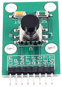
A 5 way navigation button actually has 7 different navigational settings. It has a lot of functionality in a small package.  The ‘button’ on it can be moved/pushed in 4 directions ( labeled up, down, left, right)  or pressed down. There are also two other switched buttons labeled ‘Set’ and ‘Reset’ for a total of 7 functions. Quite handy!

Here is what it looks like:

5 Way Navigation Button

COM is wired to ground. Each of the other navigation pins are wired to a pin on the STM32F103C8T6 or Arduino . Here is what the wiring looks like when it is wired to an STM32F103C8T6.

STM32F103C8T6 with a 5 Way Navigation Button Here is the Arduino IDE code for the STM32F103C8T6. When the button is moved or pressed it will light the LED and display the action on the serial console. Note that the input pin is initially configured as INPUT_PULLUP which makes the pin HIGH. When the button is pushed/moved it will make the  corresponding pin go to ground (LOW).

Here is the code for an Arduino Uno using Digital Pins (2,3,4,5,6,7,8):

Here is a top and side view of the button so you can see it looks somewhat like a joystick.

5 Way Navigation Button5 Way Navigation Button

PIR Sensor and Relay Switch to turn on a Light

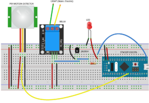
Ever wonder how a motion detector is used to turn on a light? Take a look at this graphic (made with Fritzing). It shows the circuitry that uses an STM32F103C8T6 microcontroller to control a PIR sensor and relay switch to turn on a Light.

PIR Sensor and Relay Switch to turn on a Light

Get the Fritzing source code for the above image HERE (in case you would like to modify it).  Shown below is the code for the STM32F103C8T6 microcontroller to be used in the Arduino IDE.

When motion is detected by the sensor, the relay is turned on which completes the mains circuit. Then, what ever is connected to the relay (like a light) is turned on. The motion detection is also shown by turning on the led and logging to the serial port.

To use this code in a practical situation, remove the serial port messages and change the length of time the relay switch is on.

An STM32F103C8T6 based MIDI Controller for MIDI2LR

For those of you who use Adobe Lightroom,  there is a way to use a MIDI hardware ‘box’ to control various Lightroom actions. I am told that once you use the hardware controls you will never want to go back to the software ones. There is a Lightroom plugin called MIDI2LR which interfaces various MIDI ‘boxes’ to  Lightroom. The MIDI box sends MIDI Control/Change commands to MIDI2LR which then changes them into Lightroom actions. More info on MID2LR can be found HERE.

There are several commercial MIDI controllers which do work with MID2LR, however, features and functionality differ. Since the whole idea for using the hardware controls is ease of use and productivity, I would think that Lightroom enthusiasts would want a means of creating a custom hardware solution.

It is actually relatively easy to create an STM32F103C8T6 based MIDI Controller for MIDI2LR. As a proof of concept, I built one on a breadboard to demonstrate what can be done. Here is the design layout:

An STM32F103C8T6 based MIDI Controller for MIDI2LRDownload the Fritzing diagram source code HERE.  And here is what it looks like all wired together:

An STM32F103C8T6 based MIDI Controller for MIDI2LR

The two buttons next to the display are used to control menu selections. The menu is used to set whether the buttons send MIDI Notes or Change/Control commands and also is used to select up to 5 channels.  Therefore with the 8 buttons  x ( 5 channels) x 2 (Note vs. CC commands), there is a possibility of  80 different commands to send to MIDI2LR.  The 5 channels is arbitrary and of course changeable in the code so possibilities are only limited by practicality. When a button is pressed, the MIDI CC/Note is sent to MIDI2LR and displayed on the OLED screen.

The code below was developed and sent to the STM32F103C8T6 via the Arduino IDE:

The Arduino IDE was used to develop and program the STM32F103C8T6. The IDE was also customized to use the Arduino Core for STM32 MCUs. Also note the use of the Adafruit graphics libraries to control the OLED display.

Once the code is sent, just plug in the STM32F103C8T6 via an USB-micro cable to your Windows 10 PC and it will be added as an audio device (no drivers are needed as it is automatically recognized). Install the MIDI2LR plugin and while in Lightroom you can test out the button functions and customize the functionality.

You might say that buttons are OK but dials (rotary encoders) are what is missing.  You are right, that is what is being planned for in the next step of this project. Stay tuned!

WebRTC Phone Calls via Asterisk

Are you ready for another off topic article on WebRTC?  This one is titled WebRTC Phone Calls via Asterisk. I have written about Asterisk before (HERE) and that article did have something to do with microcontrollers  😎  Asterisk is an open source full featured phone system (PBX). In my last post about WebRTC, I showed how to do video/audio sharing via WebRTC. This article shows how to turn your Web browser into a (tele)phone (using the PC audio devices and WebRTC Javascript code). With the code provided you can make and answer calls through your Asterisk system via the Web.

Of course you need an Asterisk system up and running for testing this. There are many helpful tutorials on the internet to help with that. The Asterisk wiki also has very good documentation on installing and customizing Asterisk.

The article to customize Asterisk for WebRTC is HERE. Basically, there are three configuration files that need changed to make WebRTC Phone Calls via Asterisk.  Usually these files (httpd.conf, extensions.conf, sip.conf) are found in the /etc/asterisk directory after installation .

For httpd.conf, you will need to select a port for both TLS and HTTP.  You will also need a valid SSL certificate. I am using one from Letsencrypt.org. In the example below I am using port 7070 for HTTP and 7079 for TLS.

For sip.conf , you need to specify the parameters for the phone (I am using extension 5099):

Note that WebRTC will be using the websocket protocol for communications to the Asterisk server.

In extensions.conf is where you specify the context and dialing plan so that the WebRTC enabled phone can make and receive calls:

Note: The dialing plan is where security is very important because it specifies who the  ‘phone/user’ is allowed to dial  and also what is allowed to call it.

Once Asterisk has been configured, the WebRTC code can be  accessed to try a call.  To implement the SIP and WebRTC protocols I have chosen to use the JSSIP Javascript library code (HERE).

Download  the JSSIP library and  place it (jssip.min.js) in the same Web directory as the two other files (index.html and sip.js) show below.

Here is the index.html page to enable the phone:

Here is the main Javascript code (sip.js):

Make sure to change the domain name and port to match what is configured in Asterisk. Then navigate to the index.html page and you should see this page:

WebRTC Phone Calls via Asterisk


Then put in the phone number and password  for the WebRTC phone and click Register. If all goes well, the Register button will change to ‘Registered’. Your WebRTC phone is now ready to answer or make calls.

Put in an extension to call and click the Call button. The Call button will change to match the state of the call. Any incoming calls will automatically be answered and the Call button will be updated to the state of the call. Note: WebRTC (the browser) will ask permission to use the microphone when the fist call is made or answered.

Note that diagnostic messages are logged to the web console. Un-commenting the JsSIP debug.enable in sip.js will also show a lot of interesting debug information for those curious as to what is happening behind the scenes.

Load more