I created a simple circuit using the LM317 to output 3.3 volts from a 5V or greater input voltage. Why? Because, a number of modules for the Arduino (or Pinguino) take 3.3 Volts. It’s true, some of the Arduinos do have a 3.3V voltage regulator (and thus a source of 3.3V), however, that might not have sufficient amperage. Also, if you are a fan of the DIY (Do-It-Yourself) Pinguinos (as I am), you will need a 3.3V source to accompany them since they do not have one.
So, it is quite handy to have a 3.3V power source around! Here is what the circuit looks like:
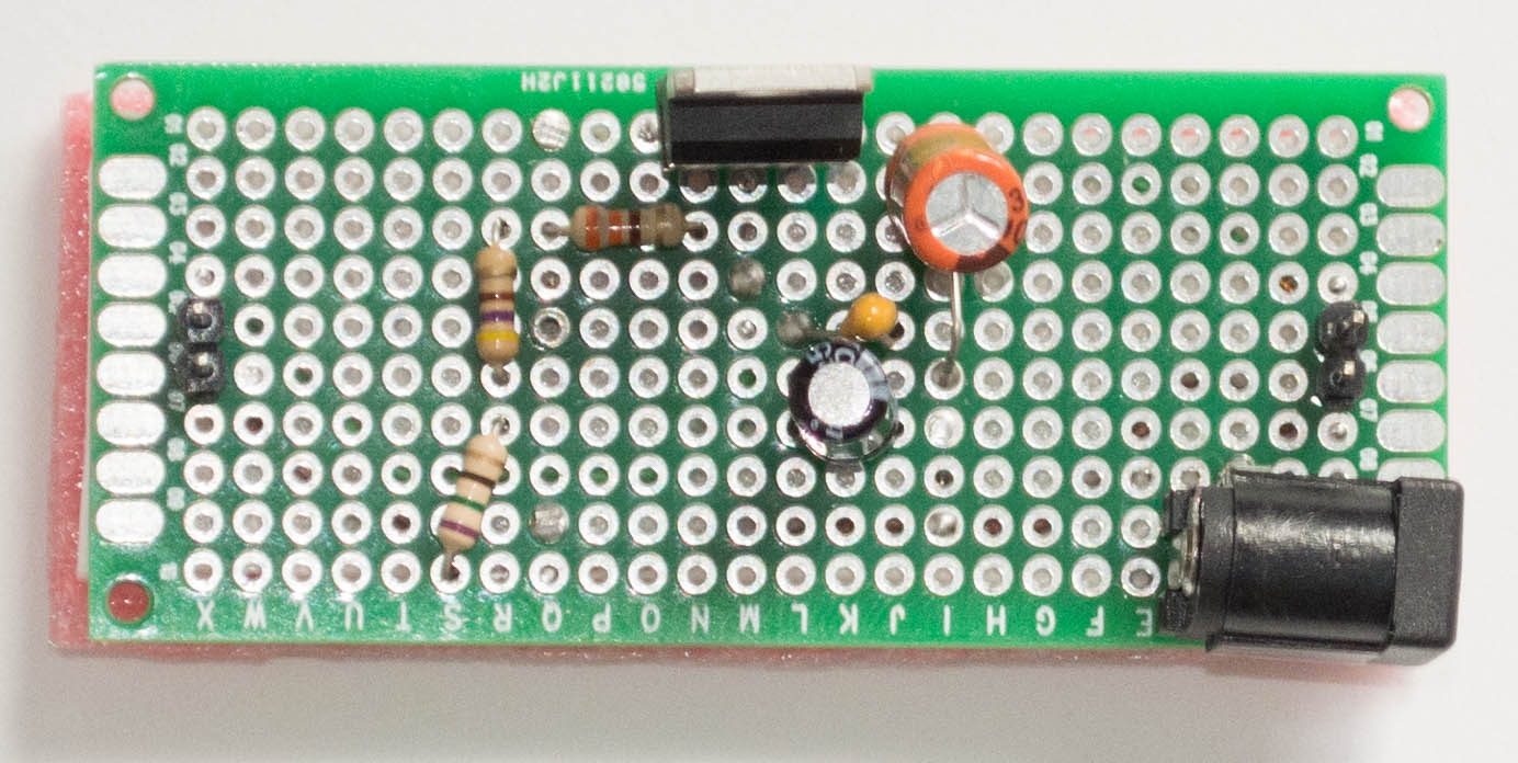

I save the foam pads, that came with PC motherboards I bought, and cut out pieces to place under the circuits I make to protect against short circuits. The pads are held in place with two-sided sticky tape.
Here Is the Fritzing circuit diagram:
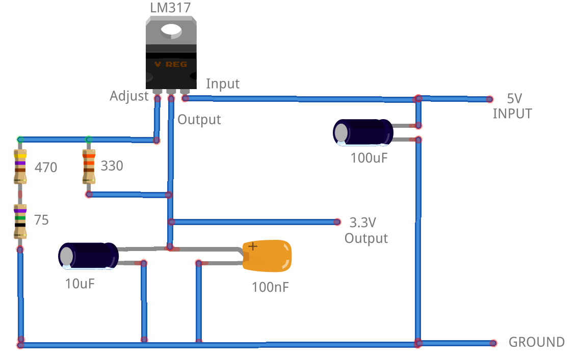
If you’d like the Fritzing source to the above diagram, download it from here.
The LM317 is an adjustable linear voltage regulator. It can take an input voltage of 3-40 Volts DC and outputs a fixed voltage from 1.2 to 37 Volts DC. The output is controlled by resistors on the adjustment pin. Here is a handy calculator to calculate the resistance needed to obtain the desired output voltage. I use 545 Ohms (470 + 75) to output the desired 3.3V.
Notice that I have a two pin header or a power jack as input source (on the right of the pictures) and the output is a two pin header (on the left in the pictures).
I tested this circuit using the ESP8266 and the NL6621-Y1 modules that I wrote about in earlier articles. These modules require 3.3V and both worked fine.
I thought about integrating this circuit on the DIY Pinguino boards I made and might do that next time I get around to making more of them. However, I think the stand alone circuit is more flexible to use. For example, you can attach a USB to RS-232 cable (like this):
 directly to the circuit (5V Input and GND) and to the wireless module (Tx and Rcv from the cable, 3.3V and GND from the circuit) and not even need an Arduino / Pinguino.
15 comments
Skip to comment form
Amazing ! I built it and the output voltage is exact 3.3 V. Beautiful and great job.
Ty
Why does this work? The min Vdrop is 3V? I’m also planning to drop 3.7v to 2.4v but I’m not sure if this can be done by LM317
Author
Are you sure of the minimum voltage drop? Take a look at the LM317 technical documentation. Also look at several of the calculators for the LM317(like https://circuitdigest.com/calculators/lm317-resistor-voltage-calculator)
What is the purpose of those capacitors?
Author
The capacitors provide current when the source doesn’t. They would not be needed if the power source was perfect but is that ever the case. You can find more info about this with a search on ‘smoothing capacitors’.
Thank you so much for this !
I used the circuit and it reduced 5v to 3.3v nicely.
But I have a question ? Can it used for reducing more than 5v to 3.3v ?
For example reducing 9v to 3.3v ?
Author
Yes, it can.. and the post mentions this specifically.
one more question …..
if i reach battery voltage of 5v to 3.3v what will be the output of that circuit?…
so directly i wanna ask is if input voltage is 3.3v than what will be the output voltage??
Author
Hi,
Please read the post more carefully. There is a link for a handy calculator that shows what the output voltage is based on the input voltage and the adjustment (resistor).
Earl
I’m going to try build it
nice work, also i noticed that the datasheet (https://www.st.com/resource/en/datasheet/lm317.pdf) say:
– Output current in excess of 1.5 A
– They are designed to supply more than 1.5 A of load current
what does this mean?
i have a LM317T, i suppose it has the same properties?
Author
Check the manufacturers’ sheet for the LM317T and then you will be sure.
As I see, it does not have a separate sheet, it is bundled in the LM317 datasheet.
So my question is: what is this 1.5 A barrier means? An ESP8266 won’t draw that much, will it function correctly?
Anyways I will build this in some days…
Author
I am using that circuit to power an ESP8266 and have not had any problems.
Nice circuit.
I used a 360 and a 220 ohm resistors (5%) and hit 3.3v very closely. Saves a resistor.
Thanks for sharing.
BB