Rotary encoders are useful for many things. Here is what they look like (with and without the button):
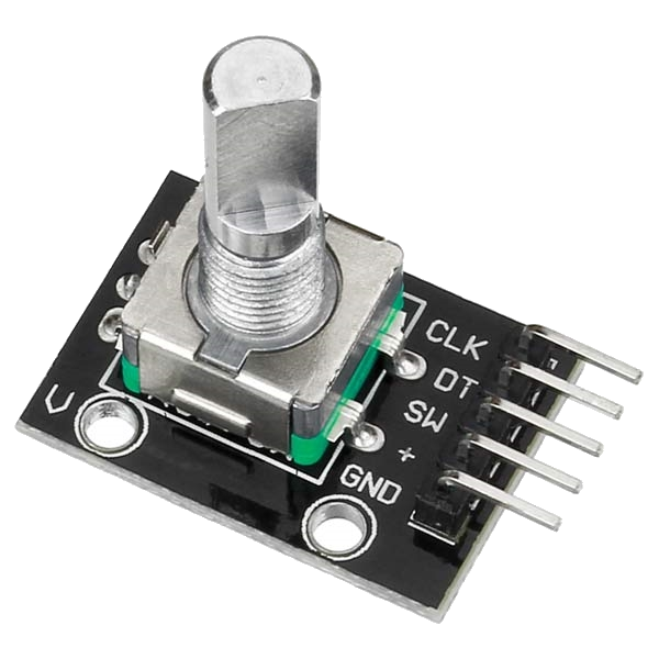

They have 5 connections (Power, Ground, Data, Clock and Switch). The button can be turned (continuously in any direction) and it can also be pushed down .
The switch connection monitors the button push whereas the data and clock connections are used to monitor the direction and turn of the button. There are many tutorials on how these ‘encoders’ work, for more information check this link.
Multiple encoders are needed for the MIDI2LR project that was posted here. In order to test multiple encoders , this sketch called ‘Multiple Rotary Encoders on an STM32F103C8T6’ was created:
// From: earl@microcontrollerelectronics.com
// STM32F103C8T6 with 5 Rotary Encoders
/*
             +-----------------[USB]-----------------+
  [SS2|PB12] | [31]                            [Gnd] |
 [SCK2|PB13] | [30]                  +---+     [Gnd] |
[MISO2|PB14] | [29]    +-----+       |0 0|     [3V3] |
[MOSI2|PB15] | [28]    |Reset|       |x x|   [Reset] |
       [PA8] | [27]    +-----+       |1 1|      [ 0] | [PB11|SDA2|RX3]
   [TX1|PA9] | [26]                  +---+      [ 1] | [PB10|SCL2|TX3]
  [RX1|PA10] | [25]                   ^ ^       [33] | [PB1]
 [USB-|PA11] | [24]            Boot1--+ |       [ 3] | [PB0|A0]
 [USB+|PA12] | [23]            Boot0----+       [ 4] | [PA7|A1|MOSI1]
      [PA15] | [20]                             [ 5] | [PA6|A2|MISO1]
       [PB3] | [19]        +-----------+        [ 6] | [PA5|A3|SCK1]
       [PB4] | [18]        | STM32F103 |        [ 7] | [PA4|A4|SS1]
       [PB5] | [17]        | Blue Pill |        [ 8] | [PA3|A5|RX2]
  [SCL1|PB6] | [16]        +-----------+        [ 9] | [PA2|A6|TX2]
  [SDA1|PB7] | [15]                             [10] | [PA1|A7]
       [PB8] | [32]                             [11] | [PA0|A8]
       [PB9] | [PB9]                            [12] | [PC15]
             | [5V]      +---------------+      [13] | [PC14]
             | [Gnd]     |    ST-Link    |      [14] | [PC13|LED]
             | [3V3]     |3V3 DIO CLK GND|     [Vbat]|
             +-------------+---+---+---+-------------+
                           |   |   |   |

PA9  TX / PA10 RX Serial Upload Serial
PA2  TX / PA3  RX Serial1
PB10 TX / PB11 RX Serial2

*/

// The Rotary Encoder Pins are wired CLK,DT,SW,CLK,DT,SW ..

const uint8_t pins[] = { PB11,PB10,PB1,PB0,PA7,PA6,PA5,PA4,PA3,PA2,PA1,PA0,PB12,PB13,PB14 };
#define NUMPINS (sizeof(pins) / sizeof(pins[0]))

// Number of Rotary Encoders
#define NUMRE (NUMPINS / 3)

int state[]     = {0,0,0,0,0};
int laststate[] = {0,0,0,0,0};
int counter[]   = {0,0,0,0,0};
char buf[80];

void setup() {
  Serial.begin (115200);
  for(int i=0,j=0,k=1,b=2;i<NUMRE;++i,j+=3,k+=3,b+=3) {
    pinMode(pins[j],INPUT);
    pinMode(pins[k],INPUT);
    pinMode(pins[b],INPUT_PULLUP);
  }
  for(int i=0,j=0;i<NUMRE;++i,j+=3) laststate[i] = digitalRead(pins[j]);
}

void loop() {
  for(int i=0,j=0,k=1,b=2;i<NUMRE;++i,j+=3,k+=3,b+=3) {
    state[i] = digitalRead(pins[j]);
    if (laststate[i] != state[i]) {
      if (digitalRead(pins[k]) != state[i]) ++counter[i];
      else                                  --counter[i];
      sprintf(buf,"RE: %d Position: %d",i+1,counter[i]);
      Serial.println(buf);
    }
    laststate[i] = state[i];
    if (digitalRead(pins[b]) == LOW) {
       sprintf(buf,"RE: %d Button Push",i+1);
       Serial.println(buf);
       while(digitalRead(pins[b]) == LOW);
       delay(50);
    }
  }
}
The pins are set up in an array so that the code can quickly ‘scan’ through them and not miss any state changes.
Notice that the switch (button press) pins are set up as INPUT_PULLUP. If they go ‘LOW’ then the button was pushed.
Here is what the wiring looks like:
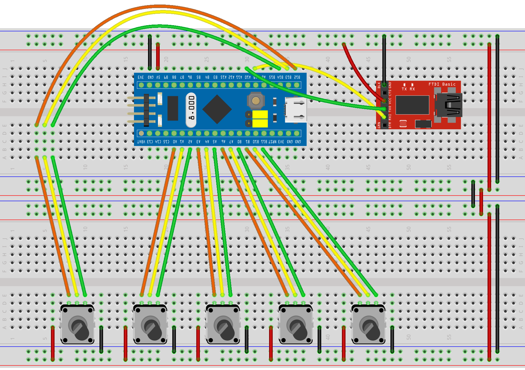
Get the fritzing.org code for that wiring graphic here (so it can be modified if needed).
2 comments
Great project. I was searching for this. I’m new with arduino and I want to use this as a VTS Plugin controller. For that propuse I need to use MIDI. I saw the other project that you made with buttons instead of the encoders but I have no idea on how change the code to use midi with this configuration. Any help will be apreciated.
Thanks in advance!
Author
Check out the other posts where I use the STM32F103C8T6 with midi software.
https://microcontrollerelectronics.com/an-stm32f103c8t6-based-midi-controller-for-midi2lr-updated/