
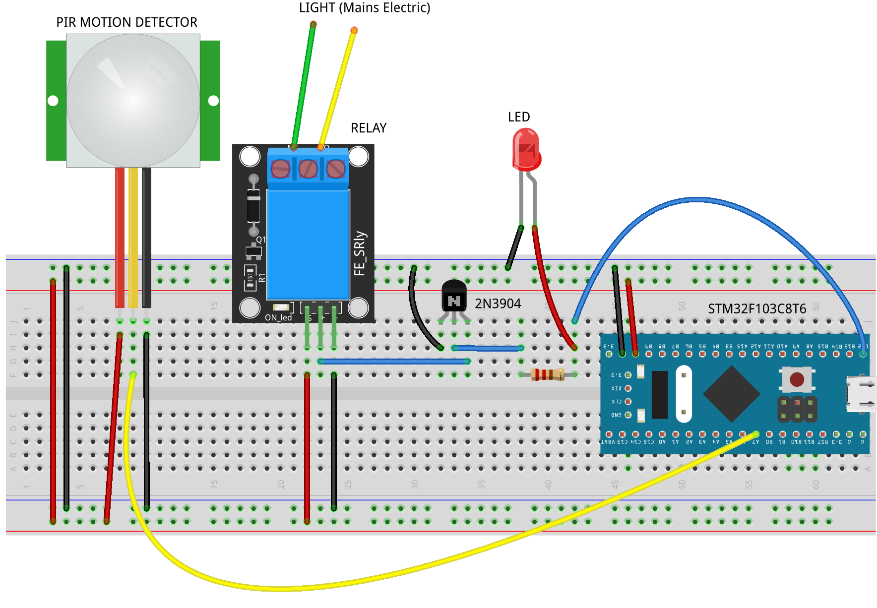
Ever wonder how a motion detector is used to turn on a light? Take a look at this graphic (made with Fritzing). It shows the circuitry that uses an STM32F103C8T6 microcontroller to control a PIR sensor and relay switch to turn on a Light.
Get the Fritzing source code for the above image HERE (in case you would like to modify it). Shown below is the code for the STM32F103C8T6 microcontroller to be used in the Arduino IDE.
//
// STM32F103C8T6 is used to turn on a relay switch
// when motion is detected by a PIR (motion sensor)
// from earl@microcontrollerelectronics.com

/*
             +-----------------[USB]-----------------+
  [SS2|PB12] | [31]                            [Gnd] |
 [SCK2|PB13] | [30]                  +---+     [Gnd] |
[MISO2|PB14] | [29]    +-----+       |0 0|     [3V3] |
[MOSI2|PB15] | [28]    |Reset|       |x x|   [Reset] |
       [PA8] | [27]    +-----+       |1 1|      [ 0] | [PB11|SDA2|RX3]
   [TX1|PA9] | [26]                  +---+      [ 1] | [PB10|SCL2|TX3]
  [RX1|PA10] | [25]                   ^ ^       [33] | [PB1]
 [USB-|PA11] | [24]            Boot1--+ |       [ 3] | [PB0|A0]
 [USB+|PA12] | [23]            Boot0----+       [ 4] | [PA7|A1|MOSI1]
      [PA15] | [20]                             [ 5] | [PA6|A2|MISO1]
       [PB3] | [19]     +---------------+       [ 6] | [PA5|A3|SCK1]
       [PB4] | [18]     | STM32F103C8T6 |       [ 7] | [PA4|A4|SS1]
       [PB5] | [17]     |   Blue Pill   |       [ 8] | [PA3|A5|RX2]
  [SCL1|PB6] | [16]     +---------------+       [ 9] | [PA2|A6|TX2]
  [SDA1|PB7] | [15]                             [10] | [PA1|A7]
       [PB8] | [32]                             [11] | [PA0|A8]
       [PB9] | [PB9]                            [12] | [PC15]
             | [5V]      +---------------+      [13] | [PC14]
             | [Gnd]     |    ST-Link    |      [14] | [PC13|LED]
             | [3V3]     |3V3 DIO CLK GND|     [Vbat]|
             +-------------+---+---+---+-------------+
                           |   |   |   |

*/

#define pirPin    PA7
#define switchPin PB12

int calibrationTime = 30;

long unsigned int lowIn;
long unsigned int pause = 10000;
boolean lockLow = true;
boolean takeLowTime;

void setup() {
  Serial.begin(9600);
  pinMode(switchPin,OUTPUT);
  pinMode(pirPin, INPUT);
  digitalWrite(PB12,LOW);
  Serial.print("calibrating sensor ");
  for(int i = 0; i < calibrationTime; i++){
    Serial.print(".");
    delay(1000);
  }
  Serial.println(" done");
  Serial.println("SENSOR ACTIVE");
}

void loop() {
 if(digitalRead(pirPin) == HIGH){
   digitalWrite(switchPin, HIGH);   //the led visualizes the sensors output pin state
   if(lockLow){
     //makes sure we wait for a transition to LOW before any further output is made:
     lockLow = false;
     Serial.println("---");
     Serial.print("motion detected at ");
     Serial.print(millis()/1000);
     Serial.println(" sec");
     delay(50);
   }
   takeLowTime = true;
 }
 if(digitalRead(pirPin) == LOW){
   digitalWrite(switchPin, LOW);  //the led visualizes the sensors output pin state
   if(takeLowTime){
     lowIn = millis();          //save the time of the transition from high to LOW
     takeLowTime = false;       //make sure this is only done at the start of a LOW phase
   }
   //if the sensor is low for more than the given pause,
   //we assume that no more motion is going to happen
   if(!lockLow && millis() - lowIn > pause){
     //makes sure this block of code is only executed again after
     //a new motion sequence has been detected
     lockLow = true;
     Serial.print("motion ended at ");
     Serial.print((millis() - pause)/1000);
     Serial.println(" sec");
     delay(50);
   }
 }
}
When motion is detected by the sensor, the relay is turned on which completes the mains circuit. Then, what ever is connected to the relay (like a light) is turned on. The motion detection is also shown by turning on the led and logging to the serial port.
To use this code in a practical situation, remove the serial port messages and change the length of time the relay switch is on.
Recent Comments