
There is a lot of electrical ‘noise’ all around us that we can’t see or sense as humans. However, in this day and time we have a great number of electronic devices which can sense what we can’t. Actually, it is these vary same electronic devices in most cases which are the cause of all the ‘noise’. 😯
For example, if you are interested in seeing what frequencies are in the 2.4GHz range (to determine what channel might be best for your WiFi router), you will be interested in the nRF24L01 module from Nordic Semiconductor. Here is a link to the product specifications. They look like this:
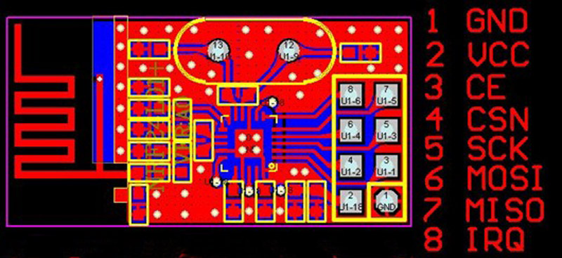
Here is the Fritzing diagram to wire it up to an Arduino Leonardo:
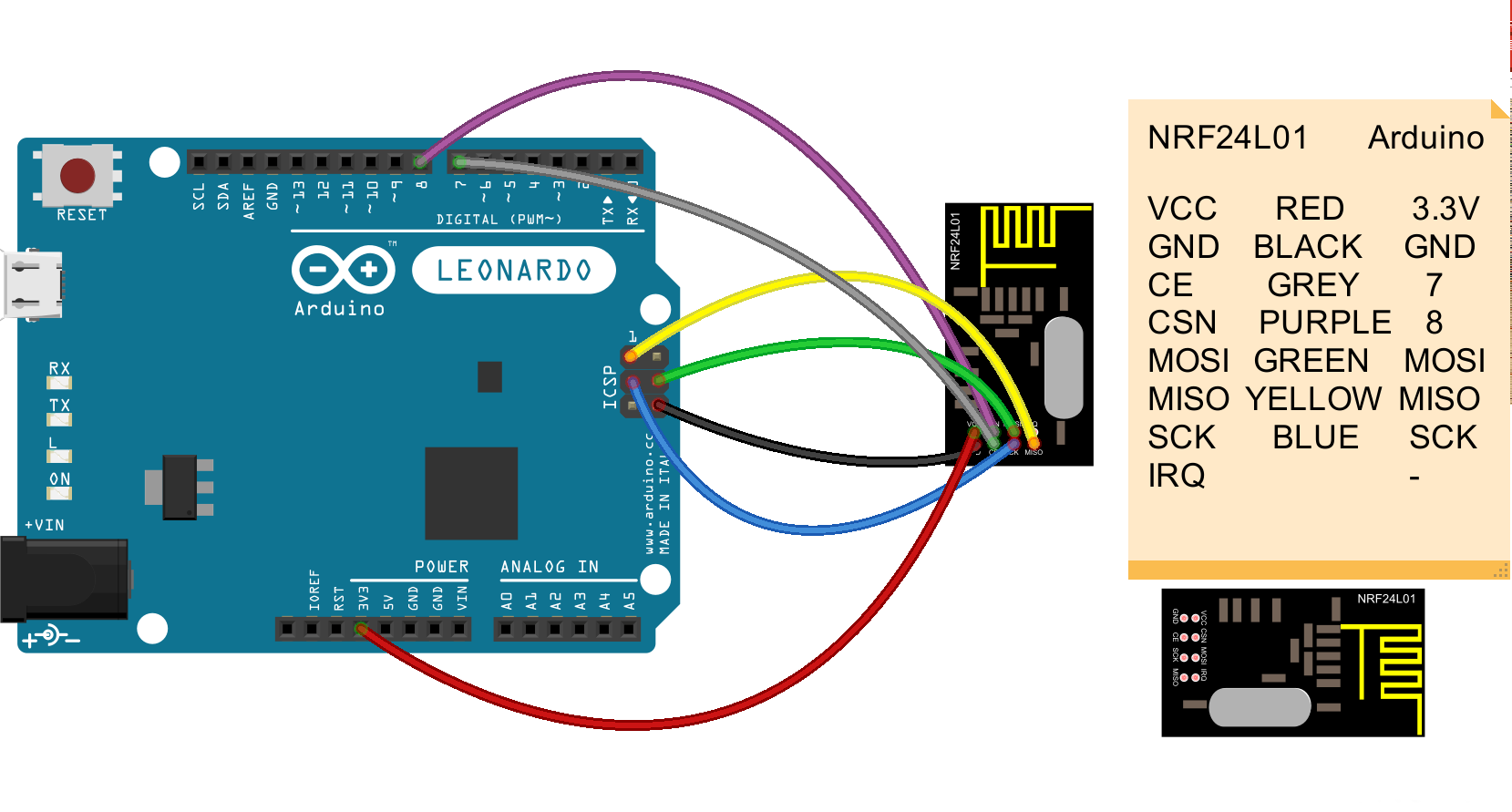
If you want to modify the Fritzing diagram, here is the source. This module uses the SPI interface to communicate. Notice that the two ‘radio’ pins in my diagram (CE – Chip Enable and CSN – Chip Select) are wired to Arduino pins 7 and 8 respectively (this must match what the code is expecting them to be which varies depending upon the library you choose). Also, you may need to place a 10 uf capacitor between +3.3v and ground to stabilize the power supply. These modules use 3.3V not 5V!
You will need an Arduino Library to control the nRF24L01 module, I used the one here. That library has a number of example sketches. The one to use (listed below called scanner.ino) wiil use the nRF24L01 module to scan the 2.4GHz frequency range. Note: I modified the code to use variables for the CE and CSN pins to make it easier to change if needed.
/*
 Copyright (C) 2011 J. Coliz <maniacbug@ymail.com>

 This program is free software; you can redistribute it and/or
 modify it under the terms of the GNU General Public License
 version 2 as published by the Free Software Foundation.
 */

/**
 * Channel scanner
 *
 * Example to detect interference on the various channels available.
 * This is a good diagnostic tool to check whether you're picking a
 * good channel for your application.
 *
 * Inspired by cpixip.
 * See http://arduino.cc/forum/index.php/topic,54795.0.html
 */

#include <SPI.h>
#include "nRF24L01.h"
#include "RF24.h"
#include "printf.h"
//
// Hardware configuration
//

// Set up nRF24L01 radio on SPI bus plus CE and CSN
// CE  - Chip Enable
// CSN - Chip Select

#define CE_PIN  7
#define CSN_PIN 8

RF24 radio(CE_PIN,CSN_PIN);

//
// Channel info
//

const uint8_t num_channels = 128;
uint8_t values[num_channels];

//
// Setup
//

void setup(void)
{
  //
  // Print preamble
  //

  Serial.begin(115200);
  printf_begin();
  printf("\n\rRF24/examples/scanner/\n\r");

  //
  // Setup and configure rf radio
  //

  radio.begin();
  radio.setAutoAck(false);

  // Get into standby mode
  radio.startListening();
  radio.stopListening();

  // Print out header, high then low digit
  int i = 0;
  while ( i < num_channels )
  {
    printf("%x",i>>4);
    ++i;
  }
  printf("\n\r");
  i = 0;
  while ( i < num_channels )
  {
    printf("%x",i&0xf);
    ++i;
  }
  printf("\n\r");
}

//
// Loop
//

const int num_reps = 100;

void loop(void)
{
  // Clear measurement values
  memset(values,0,sizeof(values));

  // Scan all channels num_reps times
  int rep_counter = num_reps;
  while (rep_counter--)
  {
    int i = num_channels;
    while (i--)
    {
      // Select this channel
      radio.setChannel(i);

      // Listen for a little
      radio.startListening();
      delayMicroseconds(225);


      // Did we get a carrier?
      if ( radio.testCarrier() ){
        ++values[i];
      }
      radio.stopListening();
    }
  }

  // Print out channel measurements, clamped to a single hex digit
  int i = 0;
  while ( i < num_channels )
  {
    printf("%x",min(0xf,values[i]&0xf));
    ++i;
  }
  printf("\n\r");
}

// vim:ai:cin:sts=2 sw=2 ft=cpp
Here is what the output looks like (basically a list of all the available channels/frequencies then a list of what the nRF24L01 found at each frequency):
RF24/examples/scanner/
00000000000000001111111111111111222222222222222233333333333333334444444444444444555555555555555566666666666666667777777777777777
0123456789abcdef0123456789abcdef0123456789abcdef0123456789abcdef0123456789abcdef0123456789abcdef0123456789abcdef0123456789abcdef
00000000000000000100000000000000001000000000000000000000000001100000000000000000000000000000000000000000000000000000000000000000
00000000000000000000000000000000000000000000000000000000000000000000000000000000000000000000000000000000000000000000000000000000
00000000000000000000000000000000000000000000000000000000000000000010111000000000000000000000000000000000000000000000000000000000
00000000000000000000000000000000000000000000000000000000000000000000000000000000000000000000000000000000000000000000000000000000
00000000000000000000000000000000000000000000000000000000000000000000000000000000000000000000000000000000000000000000000000000000
For your further investigation, there are of course, a number of sites on the internet with information about the nRF24L01 module and I find this one http://arduino-info.wikispaces.com particularly interesting and helpful.
Recent Comments