A number of sensors are powered via 12 Volts. Some, however, need 5 Volts. To power a remote DHT11 temperature sensor, I created a 12V to 5V sensor circuit.
This is the wiring diagram:
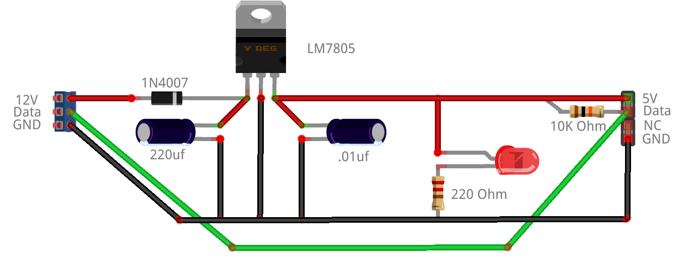
Get the Fritzing code for it HERE.
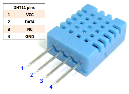
DHT11
The DHT11 needs 5 volts, ground and data. It plugs into the 12V to 5V sensor circuit via a 4 pin header slot. Notice there is a 10K pull-up resistor connected to data.
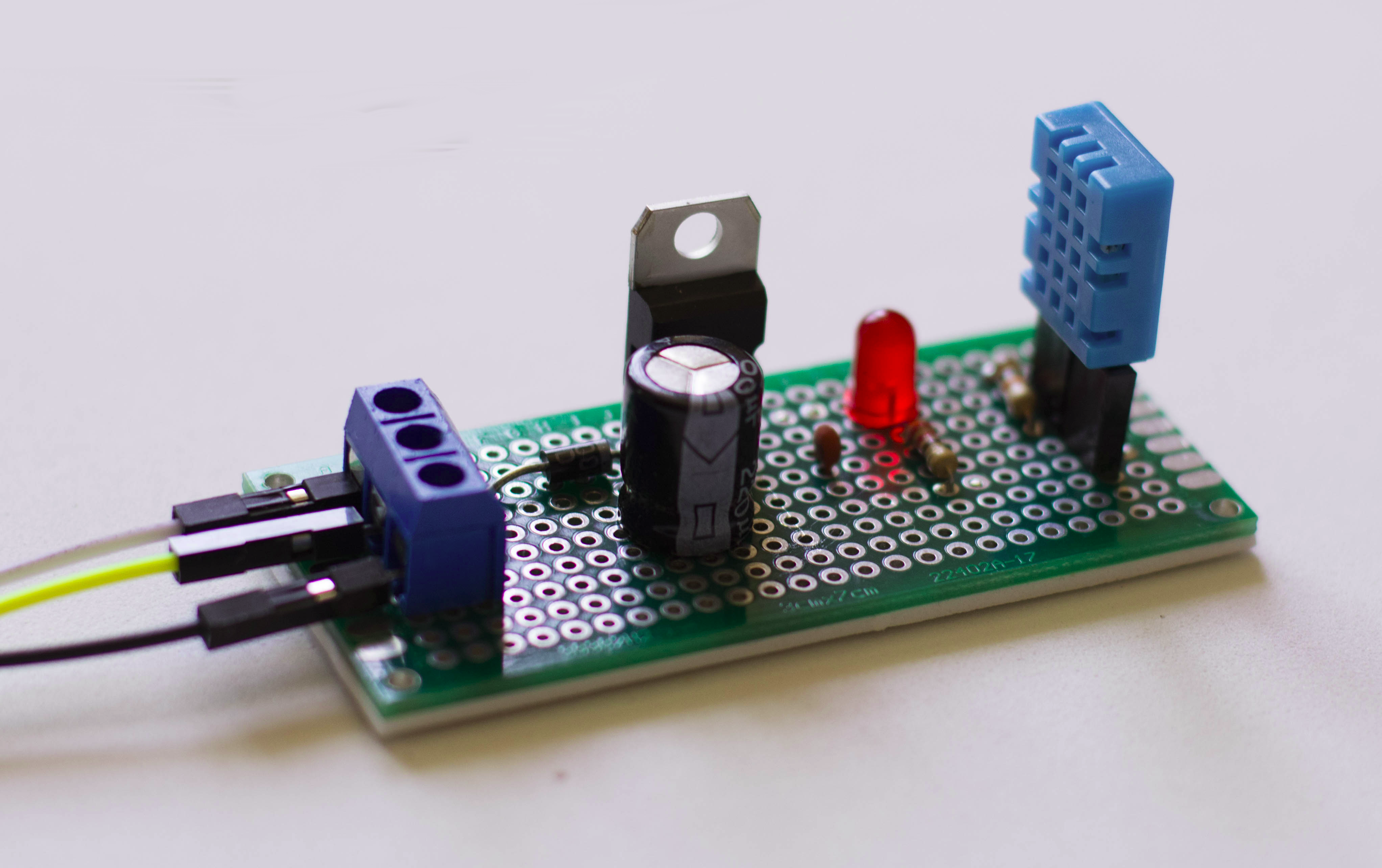
Here is what the circuit looks like with and without the DHT11 plugged in:

This type of circuit comes in handy for a larger project such as an alarm or monitoring system where sensors are some distance away from the main monitoring device such as an Arduino. For longer distance cable runs, Cat 5 cable is used which has 8 wires. Three wires can be twisted together for 12 volts. Three wires can be twisted together for ground and the remaining 2 wires can be twisted together for data. The multiple wires together increases the ‘wire size‘ and overcomes signal loss and interference in most cases.
Recent Comments