
A PhotoCell or LDR (Light Dependent Resistor), used in a circuit, allows controlling things based on light intensity.

PhotoCell / LDR (Light Dependent Resistor)
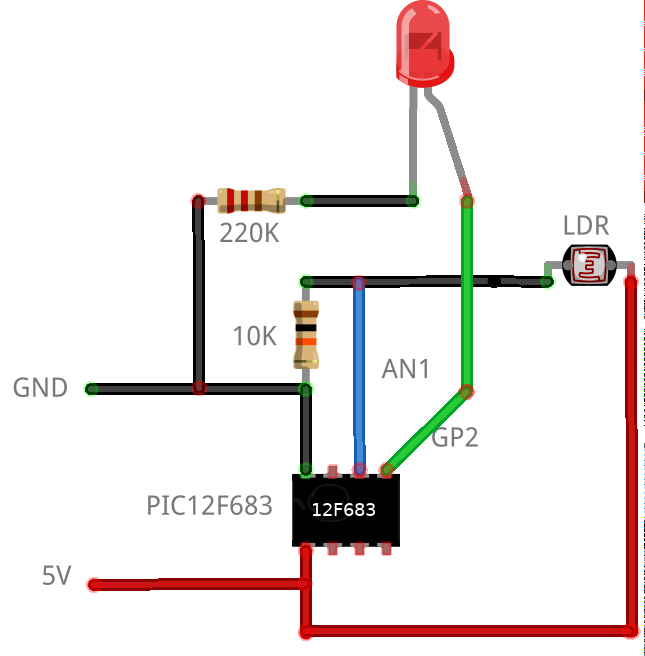
Here is a circuit showing how to wire an LDR and demonstrates how controlling things based on light intensity is possible with a little help from a microcontroller.
Controlling Things Based on Light Intensity
The thing being controlled in this circuit is simply an LED which turns On or Off. However, it could just as easily be a relay to control some other device. (Get the Fritzing source HERE for the above circuit graphic).
An analog value of the voltage which varies with light intensity can be read by a microcontroller. In this circuit, a PIC12F683 microcontroller is used. Based on that value, other circuitry can be controlled (i.e. turned On or Off).
Here is the MPLAB X IDE C source code for the PIC12F683 in the circuit shown above.
// From:  earl@microcontrollerelectronics.com
//                      _________   __________
//                     |         \_/          |
//                   __|      _               |__
//                  |  | Vdd (_)          Vss |  |
//        Vdd`  +5V |1 |                      | 8| 	VSS
//                  |__|                      |__|
//                     |                      |
//                   __|                      |__
//                  |  |              ICSPDAT |  |
// GP5 / T1CKI      |2 |                      | 7| GP0 / AN0 / CIN+
//   CLKIN          |__|                      |__| ICSPDAT / ULPWU
//                     |                      |
//                   __|                      |__
//                  |  |              ICSPCLK |  |
// T1G / AN3 / GP4  |3 |                      | 6| GP1 / AN1 / CIN- /Vref
//  OSC2 / CLKOUT   |__|                      |__| ICSPCLK
//                     |                      |
//                   __| ____                 |__
//                  |  | MCLR/Vpp             |  |
// GP3 / MCLR / VPP |4 |                      | 5| GP2 / AN2 / T0CKI / INT
//                  |__|                      |__| COUT / CCP1
//                     |                      |
//                     |______________________|
//
//                          PIC12F683
/*

 Vdd  ------ LDR
             |
 Gnd  --10K--|--------- AN1

*/

#include <xc.h>

#define _XTAL_FREQ 8000000

#pragma config FOSC  = INTOSCIO
#pragma config WDTE  = OFF
#pragma config PWRTE = OFF
#pragma config MCLRE = OFF
#pragma config CP    = OFF
#pragma config CPD   = OFF
#pragma config BOREN = OFF
#pragma config IESO  = OFF
#pragma config FCMEN = OFF

int main() {

  OSCCON = 0b00000000;
  OSCCONbits.IRCF= 0b111;  // 8Mhz
//  OSCCONbits.SCS = 0;      // FOSC <2:0> of Config Word
  OSCCONbits.SCS = 1;      // Internal Oscillator

  CMCON0 = 0b00000000;
  CMCON0bits.CM = 0b111;    // Comparator Off

  GPIO   = 0b00000000;      // Init GPIO
  TRISIO = 0b00000000;      // Init TRSIO
  TRISIObits.TRISIO1 = 1;   // AN1 Input
  TRISIObits.TRISIO3 = 1;   // GP3 Input (only)

  ANSEL  = 0b00000000;
//  ANSELbits.ADCS = 0b101;   // FOSC/16
  ANSELbits.ADCS = 0b010;   // FOSC/32
  ANSELbits.ANS1 = 1;       // AN1

  ADCON0 = 0b00000000;
  ADCON0bits.ADFM = 1;      // R1ght Justified
  ADCON0bits.VCFG = 0;      // Vdd
  ADCON0bits.CHS  = 0b01;   // AN1
  ADCON0bits.ADON = 1;      // ADC Enable

  while(1) {
    __delay_ms(5);
    ADCON0bits.GO_DONE = 1; // Go

    while (ADCON0bits.GO_DONE == 1) {}

    if ( ((ADRESH << 8) + ADRESL) > 512) GP2 = 1;
    else                                 GP2 = 0;

  }
}
The analog value varies from 0 to 1024 with 0 being no voltage and 1024 being max voltage. The code shows turning on the LED if at least 1/2 of the voltage (1/2 of 1024 = 512) is being passed by the LDR. Since the source voltage is 5V, 1/2 of it would be 2.5 volts. Depending on the application for this sort of circuit, some experimentation can be done to determine the optimum value for when to turn something On/Off.
The data sheet for the PIC12F683 is HERE. It is essential reading in order to understand how to write code for the chip. Native C coding (using the MPLAB X IDE) for PIC microcontrollers is a bit harder than the ‘sheltered’ environment of the Arduino IDE.
Yes, you can do this sort of thing with an Arduino (and the code would be easier to develop) but at a higher component cost. The components in this sample circuit are minimal, small and low cost.
Recent Comments