
I needed an easy way to calculate Microchip PIC timer 0 values, so I created the PIC Timer0 Code Generator and Calculator. If you are not familiar with PIC timers, there is a handy tutorial HERE.
The calculator part, is a spreadsheet which calculates the timings and timer 0 frequency counter needed, given the required timer (delay). The code generator part, is a Python script which generates the C source code for the PIC microcontroller XC8 compiler.
Here is what the spreadsheet looks like:
                    PIC TIMER0 Calculator

Clock Source in Mhz                     4 Mhz
Fosc                                    4000000	Hz
Fosc / 4                                1000000	Hz
Time Period                             1E-06    sec
Prescaler                               32
Timer0 Interrupt Period                 0.008192 sec
Period of Frequency Input To Timer0     3.2E-05  sec
Period of Time for each Timer0 Count    0.008192 sec

Preload (TMR0 value)                    6
Delay (Timer0 Period with Preload)      0.008	sec		0.008	sec

Required Timer                          1	sec
Number of Interrupts                    125
Basically, the required timer (i.e. delay) in seconds is specified along with the clock source in Mhz and the prescaler. Optionally a value can be specified for the TMR0 preload to adjust the timing. All the other values are automatically calculated. From the example, a 1 second delay is specified with a clock of 4Mhz, prescaler is 32 and preload is 6. The calculations show that 125 timer 0 interrupts will take 1 second.
The spreadsheet calculator can be downloaded from HERE.
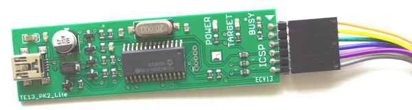
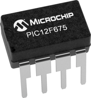
In these examples, I use the PIC12F675 programmed with a PicKit2 programmer:

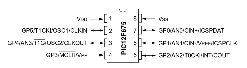
However, even though I use a PIC12F675 for the PIC Timer0 Code Generator and Calculator, it can easily be adapted to any other PIC microcontroller which needs timer 0 calculations. Actually, the spreadsheet part works works for any PIC since it does not generate code. The Python script, which generates code, would only need minor changes for other PIC microcontrollers.
Here is the Python script (gentimer0.py) which generates the C code:
#!/bin/env python
#from earl@microelectronics.com

import os,sys

if (len(sys.argv) < 4):
  print("Syntax: %s clock prescaler TMR0 period") % (sys.argv[0])
  sys.exit()

Clock     = int(sys.argv[1])
Prescaler = int(sys.argv[2])
TMR0      = int(sys.argv[3])
Period    = int(sys.argv[4])

print("")
print("//                      _________   __________")
print("//                     |         \\_/          |")
print("//                   __|      _               |__")
print("//                  |  | Vdd (_)          Vss |  |")
print("//        Vdd`  +5V |1 |                      | 8| 	VSS")
print("//                  |__|                      |__|")
print("//                     |                      |")
print("//                   __|                      |__")
print("//                  |  |              ICSPDAT |  |")
print("// GP5 / T1CKI      |2 |                      | 7| GP0 / AN0 / CIN+")
print("//   CLKIN          |__|                      |__| ICSPDAT / ULPWU")
print("//                     |                      |")
print("//                   __|                      |__")
print("//                  |  |              ICSPCLK |  |")
print("// T1G / AN3 / GP4  |3 |                      | 6| GP1 / AN1 / CIN- /Vref")
print("//  OSC2 / CLKOUT   |__|                      |__| ICSPCLK")
print("//                     |                      |")
print("//                   __| ____                 |__")
print("//                  |  | MCLR/Vpp             |  |")
print("// GP3 / MCLR / VPP |4 |                      | 5| GP2 / AN2 / T0CKI / INT")
print("//                  |__|                      |__| COUT / CCP1")
print("//                     |      PIC12F675       |")
print("//                     |______________________|")
print("//")
print("/*")
print("")
print("       PIC TIMER0 Calculator")
print("")

Fosc       = Clock * 1000000.0
Fosc4      = Fosc / 4.0
Cycle      = 1.0 / Fosc4
IntPeriod  = 1.0 / ( Fosc4 / Prescaler / 256)
FreqPeriod = 1.0 / ( Fosc4 / Prescaler)
TCount     = 256 * FreqPeriod
Delay      = ((256 - TMR0) * (Prescaler * 4)) / Fosc
NumInts    = Period / Delay

print("Clock Source in Mhz                   %s Mhz") % (Clock)
print("Fosc                                  %s Hz")  % (Fosc)
print("Fosc / 4                              %s Hz")  % (Fosc4)
print("Time Period                           %s sec") % (Cycle)
print("Prescaler                             %s")     % (Prescaler)

print("Timer0 Interrupt Period               %s sec") % (IntPeriod)
print("Period of Frequency Input To Timer0   %s sec") % (FreqPeriod)
print("Period of Time for each Timer0 Count  %s sec") % (TCount)
print("		")
print("Preload (TMR0 value)                  %s")     % (TMR0)
print("Delay                                 %s	sec") % (Delay)
print("		")
print("Required Timer                        %s sec") % (Period)
print("Number of Interrupts                  %s")     % (NumInts)
print("")
print("*/")
print("")
print("//  xc8 --chip=12F675 main.c")
print("")
print("// CONFIG")
print("#pragma config FOSC  = INTRCIO  // Oscillator Selection bits")
print("                                // (INTOSC oscillator: I/O function on GP4/OSC2/CLKOUT pin, I/O function on GP5/OSC1/CLKIN)")
print("#pragma config WDTE  = OFF      // Watchdog Timer Enable bit (WDT disabled)")
print("#pragma config PWRTE = OFF      // Power-Up Timer Enable bit (PWRT disabled)")
print("#pragma config MCLRE = OFF      // GP3/MCLR pin function select")
print("                                // (GP3/MCLR pin function is digital I/O, MCLR internally tied to VDD)")
print("#pragma config BOREN = OFF      // Brown-out Detect Enable bit (BOD disabled)")
print("#pragma config CP    = OFF      // Code Protection bit (Program Memory code protection is disabled)")
print("#pragma config CPD   = OFF      // Data Code Protection bit (Data memory code protection is disabled)")
print("")
print("#include <xc.h>")
print("")
print("#define _XTAL_FREQ %s") % (int(Fosc))
print("")
print("#define Timer0_Counter %s //Timer0 interrupt count") % (int(NumInts))
print("unsigned int cycles = 0;")
print("")
print("void interrupt isr(void) {")
print("//If T0IF: TMR0 Overflow Interrupt Flag bit equal 1, service timer interrupt")
print("  if (T0IF == 1) { ")
print("    cycles++;")
print("    TMR0 = %s;  // Preload timer register") % (TMR0)
print("    T0IF = 0;")
print("  }")
print("} ")
print("")
print("void main(void) {")
print("  OSCCAL     = __osccal_val(); // Load Oscillator Calibration")
print("  VRCON      = 0x00;           // Disable voltage reference")
print("  CMCON      = 0b00000111;     // Disable comparator")
print("  ANSEL      = 0x00;           // A/D disabled")
print("  GPIO       = 0;              // Clear GPIO")
print("  TRISIO     = 0b00001111;     // Set GPIO4 AND GPIO5 as outputs. Set GPIO0, GPIO2, GPI01 and GPIO3 as inputs")
print("  WPU        = 0;              // Disable all weak pull up")
print("  INTCON     = 0b10100000;     // Global Interrupt Enabled and TMR0 Overflow Interrupt Enabled")
print("  TMR0       = % -8s;       // Preload timer register") % (TMR0)

if (Prescaler == 2):   print("  OPTION_REG = 0b00000000;     // Start Timer0 and set Prescaler to 1:2")
if (Prescaler == 4):   print("  OPTION_REG = 0b00000001;     // Start Timer0 and set Prescaler to 1:4")
if (Prescaler == 8):   print("  OPTION_REG = 0b00000010;     // Start Timer0 and set Prescaler to 1:8")
if (Prescaler == 16):  print("  OPTION_REG = 0b00000011;     // Start Timer0 and set Prescaler to 1:16")
if (Prescaler == 32):  print("  OPTION_REG = 0b00000100;     // Start Timer0 and set Prescaler to 1:32")
if (Prescaler == 64):  print("  OPTION_REG = 0b00000101;     // Start Timer0 and set Prescaler to 1:64")
if (Prescaler == 128): print("  OPTION_REG = 0b00000110;     // Start Timer0 and set Prescaler to 1:128")
if (Prescaler == 256): print("  OPTION_REG = 0b00000111;     // Start Timer0 and set Prescaler to 1:256")

print("")
print("  GP4 = 1;")
print("  while (1) {")
print("    if (cycles >= Timer0_Counter) {")
print("      cycles = 0;")
print("// Add code here - timer expired")
print("      GP4 ^= 1; // Toggle LED on GP4")
print("")
print("    }")
print("// Main Code goes here")
print("")
print("  }")
print("}")
Here is the command to run it:
./gentimer0.py 4 32 6 1 >timer.c
and here is the resultant output:
//                      _________   __________
//                     |         \_/          |
//                   __|      _               |__
//                  |  | Vdd (_)          Vss |  |
//        Vdd`  +5V |1 |                      | 8| 	VSS
//                  |__|                      |__|
//                     |                      |
//                   __|                      |__
//                  |  |              ICSPDAT |  |
// GP5 / T1CKI      |2 |                      | 7| GP0 / AN0 / CIN+
//   CLKIN          |__|                      |__| ICSPDAT / ULPWU
//                     |                      |
//                   __|                      |__
//                  |  |              ICSPCLK |  |
// T1G / AN3 / GP4  |3 |                      | 6| GP1 / AN1 / CIN- /Vref
//  OSC2 / CLKOUT   |__|                      |__| ICSPCLK
//                     |                      |
//                   __| ____                 |__
//                  |  | MCLR/Vpp             |  |
// GP3 / MCLR / VPP |4 |                      | 5| GP2 / AN2 / T0CKI / INT
//                  |__|                      |__| COUT / CCP1
//                     |      PIC12F675       |
//                     |______________________|
//
/*

       PIC TIMER0 Calculator

Clock Source in Mhz                   4 Mhz
Fosc                                  4000000.0 Hz
Fosc / 4                              1000000.0 Hz
Time Period                           1e-06 sec
Prescaler                             32
Timer0 Interrupt Period               0.008192 sec
Period of Frequency Input To Timer0   3.2e-05 sec
Period of Time for each Timer0 Count  0.008192 sec

Preload (TMR0 value)                  6
Delay                                 0.008	sec

Required Timer                        1 sec
Number of Interrupts                  125.0

*/

//  xc8 --chip=12F675 main.c

// CONFIG
#pragma config FOSC  = INTRCIO  // Oscillator Selection bits
                                // (INTOSC oscillator: I/O function on GP4/OSC2/CLKOUT pin, I/O function on GP5/OSC1/CLKIN)
#pragma config WDTE  = OFF      // Watchdog Timer Enable bit (WDT disabled)
#pragma config PWRTE = OFF      // Power-Up Timer Enable bit (PWRT disabled)
#pragma config MCLRE = OFF      // GP3/MCLR pin function select
                                // (GP3/MCLR pin function is digital I/O, MCLR internally tied to VDD)
#pragma config BOREN = OFF      // Brown-out Detect Enable bit (BOD disabled)
#pragma config CP    = OFF      // Code Protection bit (Program Memory code protection is disabled)
#pragma config CPD   = OFF      // Data Code Protection bit (Data memory code protection is disabled)

#include <xc.h>

#define _XTAL_FREQ 4000000

#define Timer0_Counter 125 //Timer0 interrupt count
unsigned int cycles = 0;

void interrupt isr(void) {
//If T0IF: TMR0 Overflow Interrupt Flag bit equal 1, service timer interrupt
  if (T0IF == 1) {
    cycles++;
    TMR0 = 6;  // Preload timer register
    T0IF = 0;
  }
}

void main(void) {
  OSCCAL     = __osccal_val(); // Load Oscillator Calibration
  VRCON      = 0x00;           // Disable voltage reference
  CMCON      = 0b00000111;     // Disable comparator
  ANSEL      = 0x00;           // A/D disabled
  GPIO       = 0;              // Clear GPIO
  TRISIO     = 0b00001111;     // Set GPIO4 AND GPIO5 as outputs. Set GPIO0, GPIO2, GPI01 and GPIO3 as inputs
  WPU        = 0;              // Disable all weak pull up
  INTCON     = 0b10100000;     // Global Interrupt Enabled and TMR0 Overflow Interrupt Enabled
  TMR0       = 6       ;       // Preload timer register
  OPTION_REG = 0b00000100;     // Start Timer0 and set Prescaler to 1:32

  GP4 = 1;
  while (1) {
    if (cycles >= Timer0_Counter) {
      cycles = 0;
// Add code here - timer expired
      GP4 ^= 1; // Toggle LED on GP4

    }
// Main Code goes here

  }
}
The source is complied (via the Microchip XC8 compiler) with this command:
/opt/microchip/xc8/v1.45/bin/xc8 --chip=12F675 timer.c
Then use the PicKit2 programmer:
 with the command:
/opt/microchip/pk2cmd-master/pk2cmd/pk2cmd -PPIC12F675 -Ftimer.hex -M -B/opt/microchip/pk2cmd-master/pk2cmd/
to send it to the chip.
 Notice, that /opt/microchip/ is where I have installed he XC8 compiler and the PicKit2 software (pk2cmd). If you have an LED on GPIO pin4, it will blink every 1 second. Basically with this code generator, one has a starting point template to add to. The comments in the code show where to put code to make it more useful.
Recent Comments