Flashrom is an amazing piece of software and a life-saver when you need it! If you’ve tried to update your BIOS before using manufacturer supplied software and something went wrong, then you know how valuable Flashrom can be. I’ve written about Flashrom and the BusPirate in a previous post HERE. However, I just found out how easy it is to use Flashrom and an Arduino at 3.3V to program (read, write and erase) various ‘flash’ chips. All Flashrom needs is a programmer to interface with. The Arduino (or Atmega 328P) can very easily and economically be made into a Flashrom programmer.
Basically a program is loaded into the Arduino to let Flashrom program through it. I am using frser-duino which Flashrom sees as a ‘serprog’ programmer. Serprog uses the FTDI chip, the serial port and SPI interfaces to do its work. More information about Flashrom using the Serprog ‘programmer’ can be found HERE. You can get the source code for frser-duino HERE.
I am using Fedora (24 as of the date of this post). Here are the commands I used to install the prerequisites and the frser-duino code into my Arduino (a DIY UNO).
dnf install git avr-* avrdude flashrom
git clone --recursive git://github.com/urjaman/frser-duino
cd frser-duino
make ftdi
avr-objcopy -j .text -j .data -O ihex frser-duino.out frser-duino.hex
avrdude -c arduino -p m328p -P /dev/ttyUSB0 -b 115200 -U flash:w:frser-duino.hex
Notice that the documented commands are not what I used as they are for a ‘real’ Arduino UNO. Since I am using an external FTDI chip, it needs to specify 115200 BAUD to program the Arduino. However, once programmed, the larger BAUD/buffer rate of 2000000 can be used to flash with. Once the code is loaded via avrdude into the Arduino, you are ready to use it with Flashrom.
One of the ‘problems’ in flashing BIOS chips is that they are usually 3.3V whereas the Arduino is usually 5V. You could use level translation circuitry to reduce the voltage but it turns out there is a much simpler way. The DIY Arduino can be run at 3.3V using an FTDI USB to Serial converter. A DIY version of an Arduino UNO can be easily made on a breadboard, PCB or perfboard.
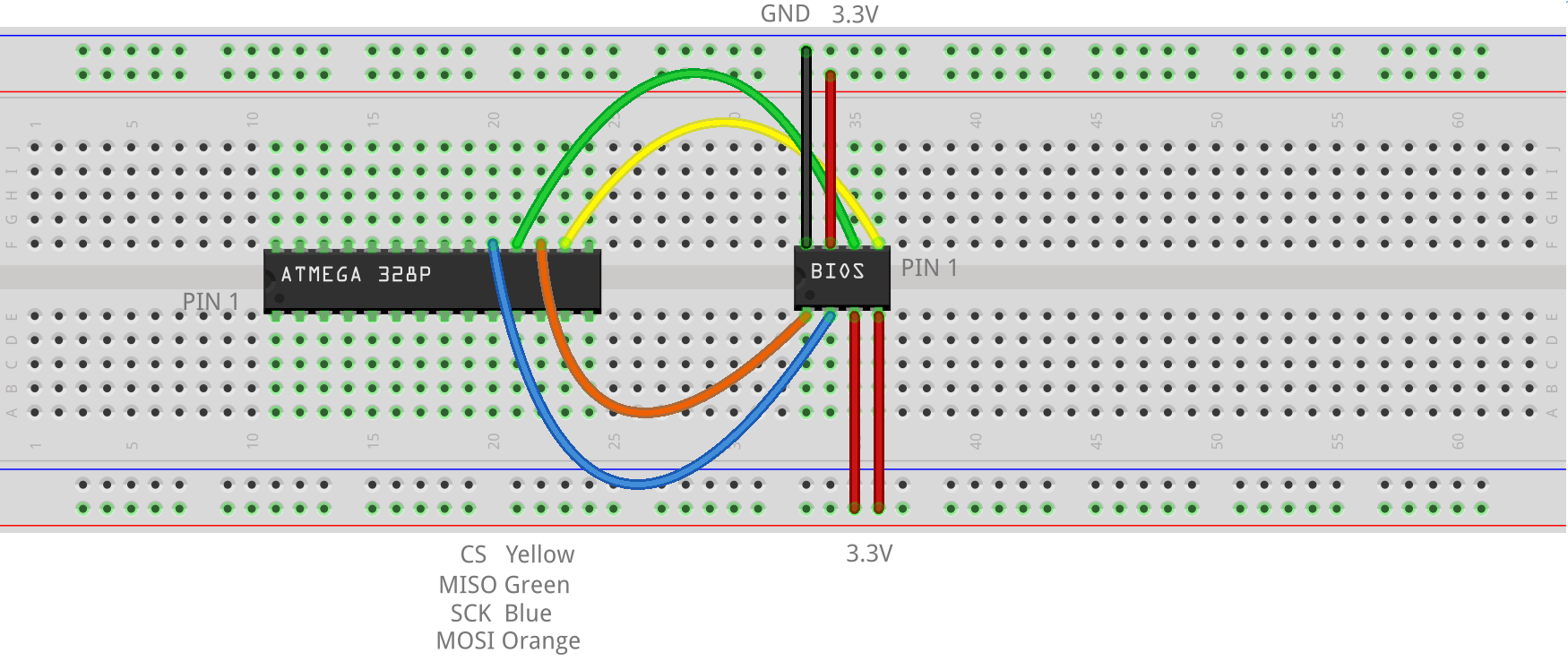
Here is an example of how an 8-pin Winbond BIOS chip is wired to the Arduino (download the Fritzing source HERE):
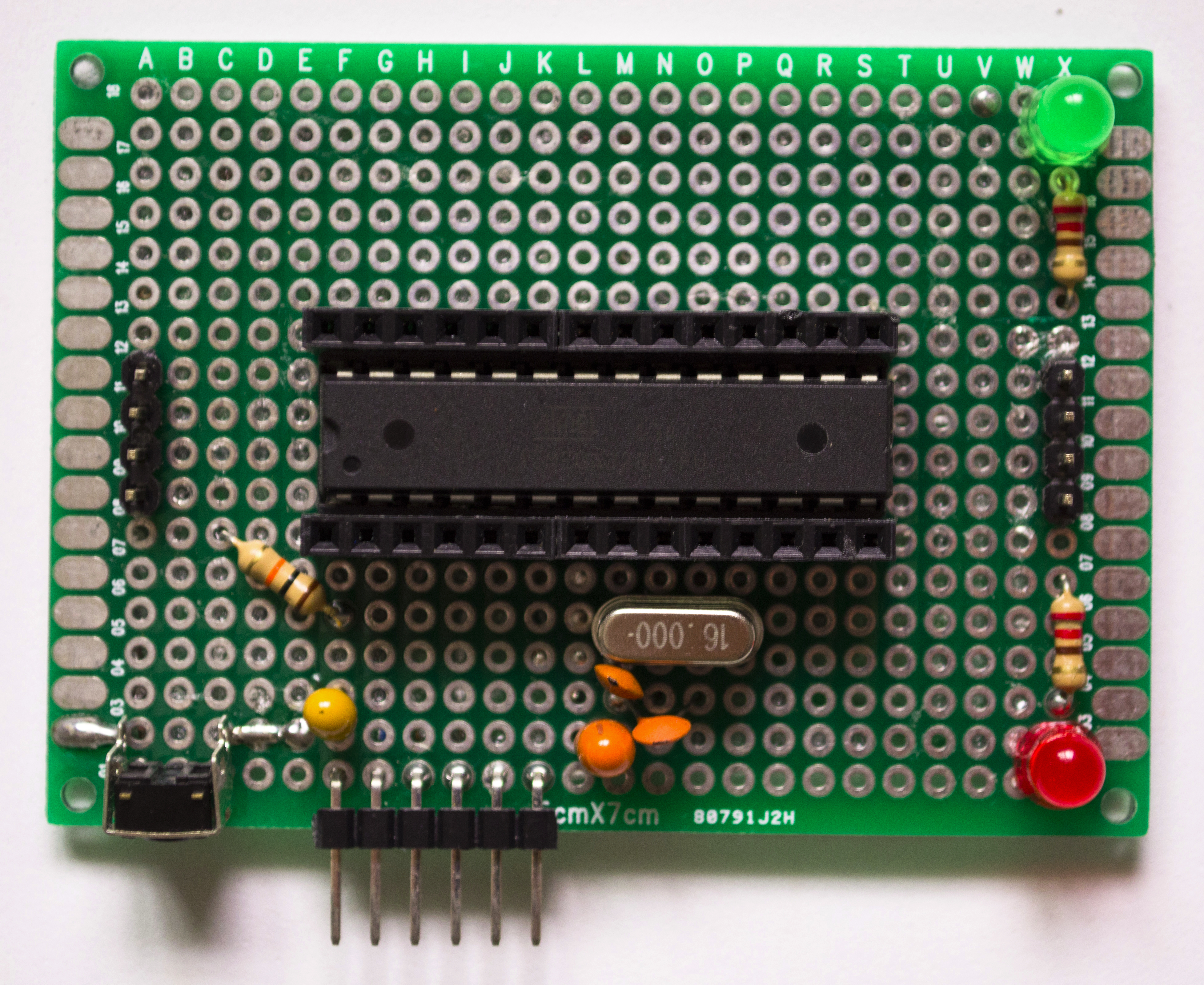 Here is a picture of my newest DIY Arduino. It is a bit different than other Arduinos I made in the past and wrote about HERE. You can see the 6 pin ICSP header on the side (to attach the FTDI USB to serial convertor). Two 14 pin female headers are soldered to the base for connectivity to any pin. There is a 4 pin header for power (left side) and a four pin header for ground (right side). This is basically a bare minimum circuit to run the ATMega 328P and function as an Arduino UNO. It runs at either 5V or 3.3V depending on the jumper of the FTDI USB to serial convertor.
 A 6 pin female-female cable is used to connect the FTDI converter to the 6 pin male ICSP header on the Arduino. The six pins are GND,CTS,PWR,TX,RX,DTR.
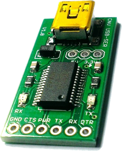
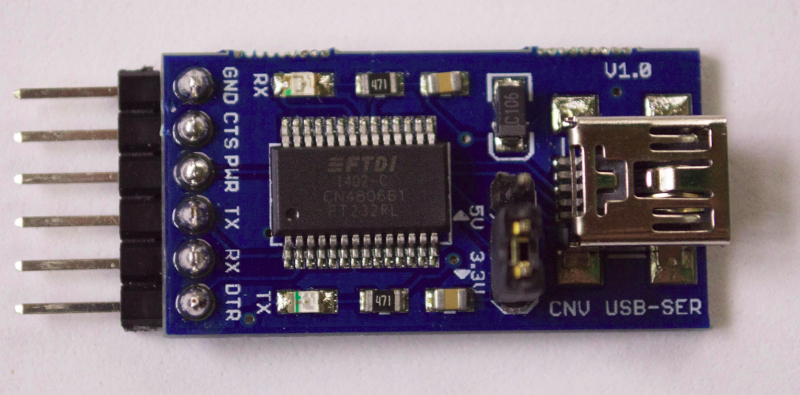
The FTDI USB to Serial Converter I use has a jumper to switch between 3.3V and 5V. I got mine from HERE.Sparkfun.com also sells one HERE. I have the jumper on 5V when I load the Arduino with the frser-duino code. Then I switch the jumper to 3.3V when I use Flashrom to program chips that need 3.3V.
Here is a picture of everything wired together:

Flashrom and an Arduino at 3.3V
If the BIOS chip is not soldered on, it can be extracted and placed on a breadboard to flash. However, if the BIOS chip is not socketed (i.e. it is soldered on), you may need an SOIC Test Clip or IC Test Hooks.
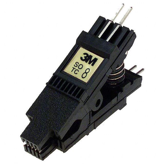
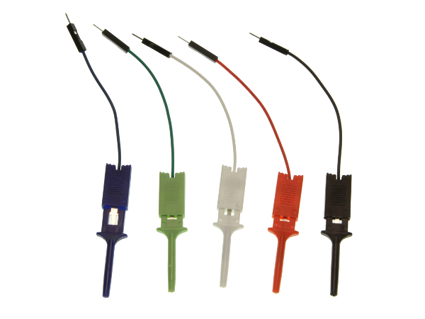
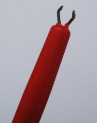
Sometimes it is hard to use the SOIC test clip due to other circuitry in the way so I prefer the IC Test Hooks. They have a tiny ‘claw’ which can be clamped onto the leg of the IC.
Here is an example command to run Flashrom and save the contents of a BIOS chip to a file:
flashrom -p serprog:dev=/dev/ttyUSB0:2000000 -r good.rom
Here is an exmaple command to just identify the flash chip:
flashrom -p serprog:dev=/dev/ttyUSB0:2000000
here are the results:
flashrom v0.9.7-r1850 on Linux 4.7.2-201.fc24.x86_64 (x86_64)
flashrom is free software, get the source code at http://www.flashrom.org

Calibrating delay loop... OK.
serprog: Programmer name is "frser-duino"
Found Winbond flash chip "W25Q32.V" (4096 kB, SPI) on serprog.
No operations were specified.
As a side note, the BIOS file to flash has to be in the proper format (ROM image). ASUS for example, distributes their BIOS files in CAP format. The ROM image has to be extracted from the CAP file with a utility like UEFITool. Alternatively, and much easier, just strip the header off the CAP file with this Linux shell script:
#!/bin/bash

for i in *.CAP; do
  x=`echo "$i"|sed -e 's/.CAP/.ROM/'`
  dd bs=2048 skip=1 if=$i of=$x
done
2 comments
Hi, congratulation for this job… I’m from Colombia, I did some things to recover a bios WINBOND 25Q32BVAIG, but it stays reading flash … help me
is this log
https://github.com/ajar04/arduino-flash-rom/wiki
Author
Did you check to make sure that your version of flashrom supports the Winbond chip you are trying to read?