
My latest project involves collecting data from a number of sensors connected to multiple Arduinos. I2C (or 2-wire) is a perfect fit for this project because I needed an easy way to connect the Arduinos and aggregate the data. With I2C, I can have one Arduino as the master and several other Arduinos as slaves. To connect the Arduinos together, I created a simple I2C 2-wire Circuit.
Here is the finished product and the wiring diagram:
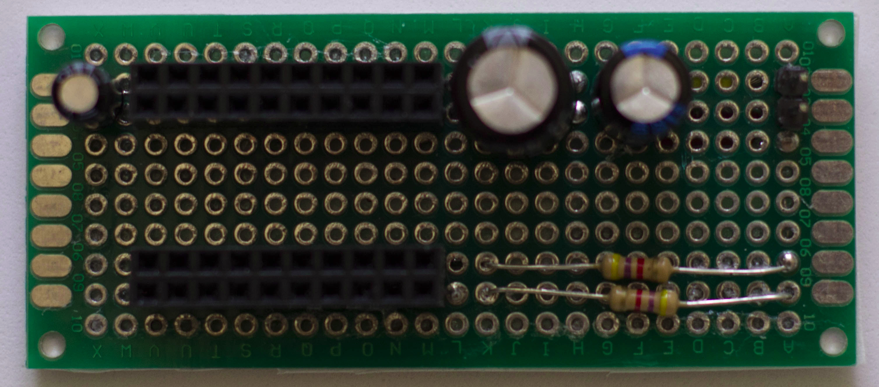
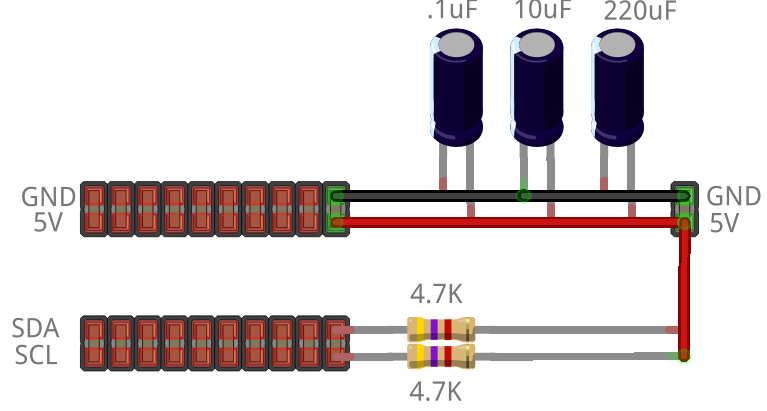
You can download the Fritzing source for the diagram HERE. As you can see from the diagram, it allows multiple connections to Power/Ground and multiple connections to SDA / SCL (the two wires used in I2C). SDA (serial data line) is used for sending data and SCL (serial clock line) is used for clocking. I2C allows for multiple master/slaves. I have one Arduino as the Master and several Arduinos as slaves. I will eventually use a Raspberry PI as the master.
If multiple Arduinos are connected on a breadboard, there can and probably will be some voltage loss. This is especially true when connecting breadboards together and ‘jumpering’ power/ground from one breadboard to another. It is best to supply each breadboard with its own source to power and ground. I built this little testing circuit to get around the power loss problem. Notice that I used 4.7K pull up resistors in this I2C 2-wire circuit. These resistors are needed to ensure the I2C bus works properly.
Recent Comments