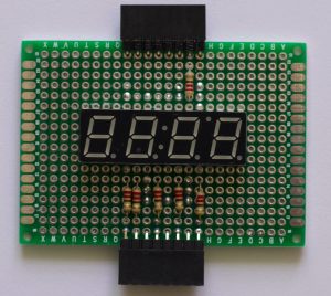
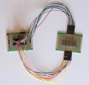
I built another handy circuit to ‘house’ a 4 character 7 segment display. It looks like this:
Basically it just ‘breaks out’ the 16 pins of the display with two 8 pin female headers. Pins 1-8 are connected to the header at the bottom and pins 9-16 are connected to the header at the top. Note that 6 220 Ohm resistors are needed to protect the LEDs.
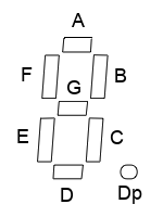
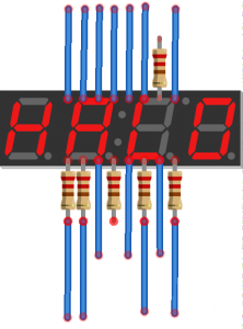 The Fritzing diagram to the right (Download Link) shows which pins select which character (colon or apostrophe) is selected to turn on and thus needs a resistor. The LEDs actually light a bar shape. Each ‘character’ is composed of 7 LEDs (or segments). The image below shows what each of the pins controls.
The LED pattern is as follows:
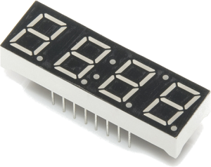 Four of these characters go together to be able to display things like time, temperature, voltage, etc.
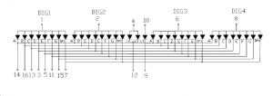
The technical manual is HERE. The pin functions (1-8 bottom and 9-16 top) are as follows:
1: Digit 1       16: B
2: Digit 2       15: G
3: D             14: A
4: Colon Anode   13: C
5: E             12: Colon Cathode
6: Digit 3       11: F
7: Decimal Point 10:Apostrophe Anode
8: Digit 4       9: Apostrophe Cathode
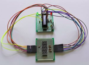
Connecting this 4 character 7 segment display to an Arduino is usually done in conjunction with 1 or more shift registers due to having so many wires. Connecting without the shift register, an arduino looks like it needs a ‘hair cut’ with so many ‘wires’ all over the place.
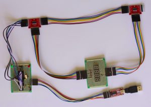
I connected my 4 character 7 segment display circuit with two 74HC595 (shift register IC) breakout modules. Each 74HC595 module controls 8 pins (1 shift register for the bottom 8 pins and one for the top 8). With these modules, only 3 wires (besides power and ground) connect to the Arduino.
Using an Arduino library designed for the 74HC595 shift register makes it easier to control the display. I like this shifter library hosted on GitHub. With it, each pin is easily referenced by number.
Here is a an Arduino sketch I created to display current voltage on the 4 character 7 segment display :
#include <Shifter.h>

#define SER_Pin   4
#define RCLK_Pin  3
#define SRCLK_Pin 2

#define NUM_REGISTERS 2

Shifter shifter(SER_Pin, RCLK_Pin, SRCLK_Pin, NUM_REGISTERS);
/*
    A
 F     B
    G
 E     C
    D

1  Digit 1
2  Digit 2
3  D
4  Colon Anode
5  E
6  Digit 3
7  Decimal Point
8  Digit 4
9  Apostrophe Cathode
10 Apostrophe Anode
11 F
12 Colon Cathode
13 C
14 A
15 G
16 B
*/

void setup(){
  shifter.clear();
  shifter.write();
}

void displayDigit(int num) {
  switch(num) {
    case 0:
      shifter.setPin(13, LOW);  // A
      shifter.setPin(15, LOW);  // B
      shifter.setPin(12, LOW);  // C
      shifter.setPin(2,  LOW);  // D
      shifter.setPin(4,  LOW);  // E
      shifter.setPin(10, LOW);  // F
      shifter.setPin(14, HIGH); // G
      shifter.setPin(6,  HIGH); // DP
      break;
    case 1:
      shifter.setPin(13, HIGH); // A
      shifter.setPin(15, LOW);  // B
      shifter.setPin(12, LOW);  // C
      shifter.setPin(2,  HIGH); // D
      shifter.setPin(4,  HIGH); // E
      shifter.setPin(10, HIGH); // F
      shifter.setPin(14, HIGH); // G
      shifter.setPin(6,  HIGH); // DP
      break;
    case 2:
      shifter.setPin(13, LOW);  // A
      shifter.setPin(15, LOW);  // B
      shifter.setPin(12, HIGH); // C
      shifter.setPin(2,  LOW);  // D
      shifter.setPin(4,  LOW);  // E
      shifter.setPin(10, HIGH); // F
      shifter.setPin(14, LOW);  // G
      shifter.setPin(6,  HIGH); // DP
      break;
    case 3:
      shifter.setPin(13, LOW);  // A
      shifter.setPin(15, LOW);  // B
      shifter.setPin(12, LOW);  // C
      shifter.setPin(2,  LOW);  // D
      shifter.setPin(4,  HIGH); // E
      shifter.setPin(10, HIGH); // F
      shifter.setPin(14, LOW);  // G
      shifter.setPin(6,  HIGH); // DP
      break;
    case 4:
      shifter.setPin(13, HIGH); // A
      shifter.setPin(15, LOW);  // B
      shifter.setPin(12, LOW);  // C
      shifter.setPin(2,  HIGH); // D
      shifter.setPin(4,  HIGH); // E
      shifter.setPin(10, LOW);  // F
      shifter.setPin(14, LOW);  // G
      shifter.setPin(6,  HIGH); // DP
      break;
    case 5:
      shifter.setPin(13, LOW);  // A
      shifter.setPin(15, HIGH); // B
      shifter.setPin(12, LOW);  // C
      shifter.setPin(2,  LOW);  // D
      shifter.setPin(4,  HIGH); // E
      shifter.setPin(10, LOW);  // F
      shifter.setPin(14, LOW);  // G
      shifter.setPin(6,  HIGH); // DP
      break;
    case 6:
      shifter.setPin(13, LOW);  // A
      shifter.setPin(15, HIGH); // B
      shifter.setPin(12, LOW);  // C
      shifter.setPin(2,  LOW);  // D
      shifter.setPin(4,  LOW);  // E
      shifter.setPin(10, LOW);  // F
      shifter.setPin(14, LOW); // G
      shifter.setPin(6,  HIGH); // DP
      break;
    case 7:
      shifter.setPin(13, LOW);  // A
      shifter.setPin(15, LOW);  // B
      shifter.setPin(12, LOW);  // C
      shifter.setPin(2,  HIGH); // D
      shifter.setPin(4,  HIGH); // E
      shifter.setPin(10, HIGH); // F
      shifter.setPin(14, HIGH); // G
      shifter.setPin(6,  HIGH); // DP
      break;
    case 8:
      shifter.setPin(13, LOW);  // A
      shifter.setPin(15, LOW);  // B
      shifter.setPin(12, LOW);  // C
      shifter.setPin(2,  LOW);  // D
      shifter.setPin(4,  LOW);  // E
      shifter.setPin(10, LOW);  // F
      shifter.setPin(14, LOW);  // G
      shifter.setPin(6,  HIGH); // DP
      break;
    case 9:
      shifter.setPin(13, LOW);  // A
      shifter.setPin(15, LOW);  // B
      shifter.setPin(12, LOW);  // C
      shifter.setPin(2,  LOW);  // D
      shifter.setPin(4,  HIGH); // E
      shifter.setPin(10, LOW);  // F
      shifter.setPin(14, LOW);  // G
      shifter.setPin(6,  HIGH); // DP
      break;
  }
}

void turnOnChar(int num) {
  switch(num) {
    case 1:
      shifter.setPin(0, HIGH);
      shifter.setPin(1, LOW);
      shifter.setPin(5, LOW);
      shifter.setPin(7, LOW);
      break;
    case 2:
      shifter.setPin(0, LOW);
      shifter.setPin(1, HIGH);
      shifter.setPin(5, LOW);
      shifter.setPin(7, LOW);
      break;
    case 3:
      shifter.setPin(0, LOW);
      shifter.setPin(1, LOW);
      shifter.setPin(5, HIGH);
      shifter.setPin(7, LOW);
      break;
    case 4:
      shifter.setPin(0, LOW);
      shifter.setPin(1, LOW);
      shifter.setPin(5, LOW);
      shifter.setPin(7, HIGH);
      break;
    default:
      break;
  }
}

void loop() {
  long vcc;
  int num4,num3,num2,num1;

  vcc = readVcc();

  num4 = (vcc / 10)    % 10;
  num3 = (vcc / 100)   % 10;
  num2 = (vcc / 1000)  % 10;
  num1 = (vcc / 10000) % 10;

  if (num1 != 0) {
   turnOnChar(1);
   displayDigit(num1);
   shifter.write();
   delay(2);
  }

  turnOnChar(2);
  displayDigit(num2);
  shifter.setPin(6,LOW);
  shifter.write();
  delay(2);

  turnOnChar(3);
  displayDigit(num3);
  shifter.write();
  delay(2);

  turnOnChar(4);
  displayDigit(num4);
  shifter.write();
  delay(2);

}

long readVcc() {
  // Read 1.1V reference against AVcc
  // set the reference to Vcc and the measurement to the internal 1.1V reference
  #if defined(__AVR_ATmega32U4__) || defined(__AVR_ATmega1280__) || defined(__AVR_ATmega2560__)
    ADMUX = _BV(REFS0) | _BV(MUX4) | _BV(MUX3) | _BV(MUX2) | _BV(MUX1);
  #elif defined (__AVR_ATtiny24__) || defined(__AVR_ATtiny44__) || defined(__AVR_ATtiny84__)
    ADMUX = _BV(MUX5) | _BV(MUX0);
  #elif defined (__AVR_ATtiny25__) || defined(__AVR_ATtiny45__) || defined(__AVR_ATtiny85__)
    ADMUX = _BV(MUX3) | _BV(MUX2);
  #else
    ADMUX = _BV(REFS0) | _BV(MUX3) | _BV(MUX2) | _BV(MUX1);
  #endif
  #if defined(__AVR_ATmega2560__)
    ADCSRB &= ~_BV(MUX5); // Without this the function always returns -1 on the ATmega2560
  #endif

  delay(2); // Wait for Vref to settle
  ADCSRA |= _BV(ADSC); // Start conversion
  while (bit_is_set(ADCSRA,ADSC)); // measuring

  uint8_t low  = ADCL; // must read ADCL first - it then locks ADCH
  uint8_t high = ADCH; // unlocks both

  long result = (high<<8) | low;

  result = 1125300L / result; // Calculate Vcc (in mV); 1125300 = 1.1*1023*1000
  return result; // Vcc in millivolts
}
Notice that I created functions to select the specific character to turn on and a function to turn on the LED segments needed to display each number digit. With the shifter library and these functions, you are all set to make something interesting! How about a multimeter?

Recent Comments