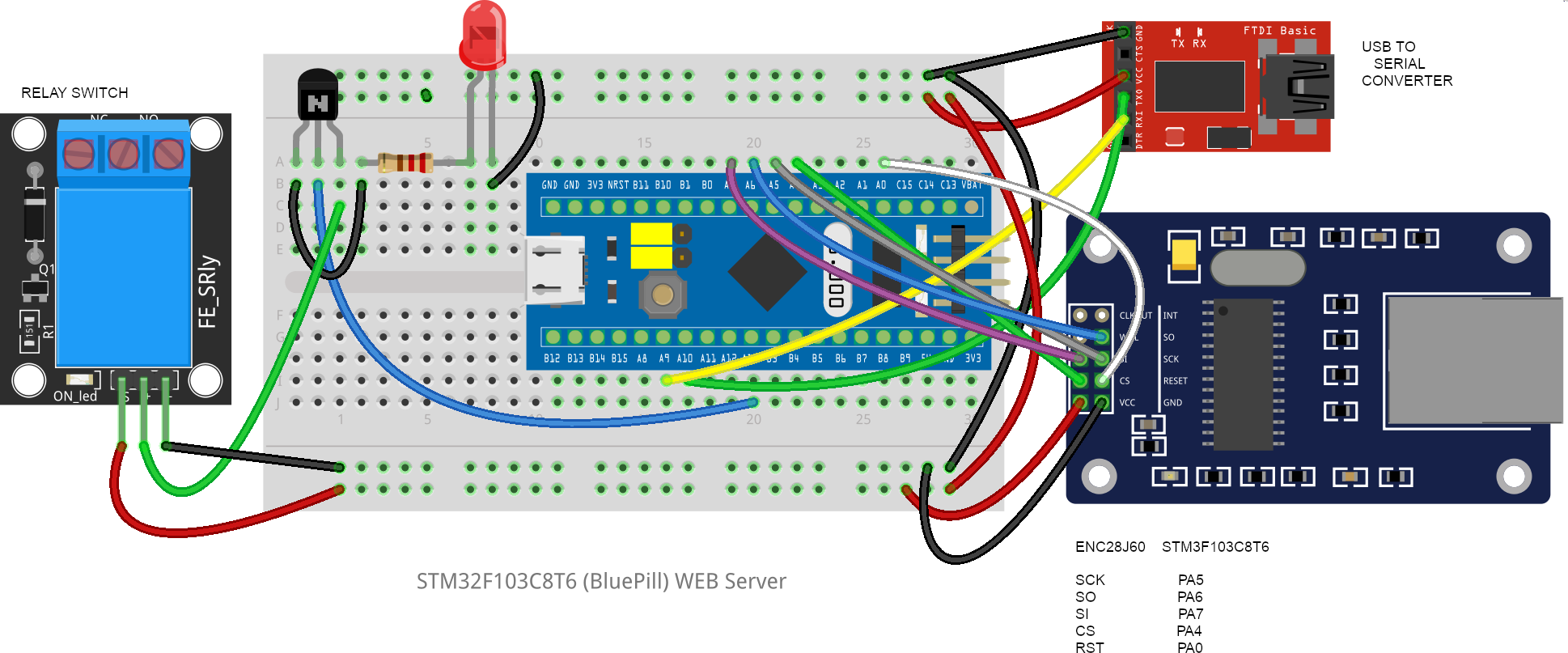
Here is the circuit showing how a Web Server on an STM32F103C8T6 can be used to control a Relay Switch:
 The Fritzing code used to create that diagram/image can be downloaded here.
An ENC28J60 ethernet module is used to connect the STM32F103C8T6 (BluePill) to a network.
Here is the source code for the sketch to load into the STM32F103C8T6 (BluePill):
/*
  Web Server

 A simple web server that shows the value of the analog input pins.
 blinks the built in LED, or toggles a Relay Switch (check the comments)

 From: earl@microcontrollerelectronics.com
 Also Demonstrates checking the ENC28J60 and keeping it from freezing.

ENC28J60  STM32F103
SCK        PA5
SO         PA6
SI         PA7
CS         PA4
RST        PA0

VCC - 5V
GND - GND

--ENC28J60--
CLK  INT
WOL  SO
SI   SCK
CS   RESET
VCC  GND

             +-----------------[USB]-----------------+
  [SS2|PB12] | [31]                            [Gnd] |
 [SCK2|PB13] | [30]                  +---+     [Gnd] |
[MISO2|PB14] | [29]    +-----+       |0 0|     [3V3] |
[MOSI2|PB15] | [28]    |Reset|       |x x|   [Reset] |
       [PA8] | [27]    +-----+       |1 1|      [ 0] | [PB11|SDA2|RX3]
   [TX1|PA9] | [26]                  +---+      [ 1] | [PB10|SCL2|TX3]
  [RX1|PA10] | [25]                   ^ ^       [33] | [PB1]
 [USB-|PA11] | [24]            Boot1--+ |       [ 3] | [PB0|A0]
 [USB+|PA12] | [23]            Boot0----+       [ 4] | [PA7|A1|MOSI1]
      [PA15] | [20]                             [ 5] | [PA6|A2|MISO1]
       [PB3] | [19]        +-----------+        [ 6] | [PA5|A3|SCK1]
       [PB4] | [18]        | STM32F103 |        [ 7] | [PA4|A4|SS1]
       [PB5] | [17]        | Blue Pill |        [ 8] | [PA3|A5|RX2]
  [SCL1|PB6] | [16]        +-----------+        [ 9] | [PA2|A6|TX2]
  [SDA1|PB7] | [15]                             [10] | [PA1|A7]
       [PB8] | [32]                             [11] | [PA0|A8]
       [PB9] | [PB9]                            [12] | [PC15]
             | [5V]      +---------------+      [13] | [PC14]
             | [Gnd]     |    ST-Link    |      [14] | [PC13|LED]
             | [3V3]     |3V3 DIO CLK GND|     [Vbat]|
             +-------------+---+---+---+-------------+
                           |   |   |   |
*/

#define BOARD_SPI1_NSS_PIN        PA4
#define BOARD_SPI1_SCK_PIN        PA5
#define BOARD_SPI1_MISO_PIN       PA6
#define BOARD_SPI1_MOSI_PIN       PA7

#include <libmaple/iwdg.h>
#include <SPI.h>
#include <UIPEthernet.h>

// ..utility\Enc28J60Network.h file -
//move readReg() subroutine def from private to public

#define NET_ENC28J60_EIR          0x1C
#define NET_ENC28J60_ESTAT        0x1D
#define NET_ENC28J60_ECON1        0x1F
#define NET_ENC28J60_EIR_RXERIF   0x01
#define NET_ENC28J60_ESTAT_BUFFER 0x40
#define NET_ENC28J60_ECON1_RXEN   0x04
#define NET_ENC28J60_CHECK_PERIOD 5000UL

#define iwdg_init_ms(N) iwdg_init(IWDG_PRE_256,((N)/5))

#define pinLED PC13
#define pinSwitch PA15
#define ETH_RS_PIN PA0

byte mac[] = { 0xDE, 0xAD, 0xBE, 0xEF, 0xFE, 0xED };

IPAddress   ipdns(192, 168,   0, 1);
IPAddress      ip(192, 168,   0, 150);
IPAddress gateway(192, 168,   0, 1);
IPAddress  subnet(255, 255, 255, 0);

EthernetServer server = EthernetServer(80);

String cdata = "";
unsigned long timer;

void setup() {
  disableDebugPorts();
  Serial.begin(115200);
  pinMode(pinLED, OUTPUT);
  pinMode(pinSwitch, OUTPUT);
  digitalWrite(pinLED,LOW);
  digitalWrite(pinSwitch,LOW);
  eth_reset();
  iwdg_init_ms(4000);
  timer = millis();
}

void eth_reset() {
  pinMode(ETH_RS_PIN, OUTPUT);
  digitalWrite(ETH_RS_PIN, LOW);
  delay(100);
  digitalWrite(ETH_RS_PIN, HIGH);
  pinMode(ETH_RS_PIN, INPUT);

  Ethernet.begin(mac, ip, ipdns, gateway, subnet);
  server.begin();
  Serial.print(F("WEB server is at "));
  Serial.println(Ethernet.localIP());

  Serial.print(F("DNS server is at "));
  Serial.println(Ethernet.dnsServerIP());
}

void loop() {
  iwdg_feed();
  Ethernet.maintain();

  if ((millis() - timer) > NET_ENC28J60_CHECK_PERIOD) {

       // Enc28J60 is Enc28J60Network class that is defined in Enc28J60Network.h
       // readReg() subroutine must be moved from private to public members area in utility\Enc28J60Network.h
       // ENC28J60 ignore all incoming packets if ECON1.RXEN is not set
       uint8_t stateEconRxen = Enc28J60.readReg((uint8_t) NET_ENC28J60_ECON1) & NET_ENC28J60_ECON1_RXEN;
       // ESTAT.BUFFER rised on TX or RX error
       // I think the test of this register is not necessary - EIR.RXERIF state checking may be enough
       uint8_t stateEstatBuffer = Enc28J60.readReg((uint8_t) NET_ENC28J60_ESTAT) & NET_ENC28J60_ESTAT_BUFFER;
       // EIR.RXERIF set on RX error
       uint8_t stateEirRxerif = Enc28J60.readReg((uint8_t) NET_ENC28J60_EIR) & NET_ENC28J60_EIR_RXERIF;
       Serial.println("---REGS---");
       Serial.println(stateEconRxen,HEX);
       Serial.println(stateEstatBuffer,HEX);
       Serial.println(stateEirRxerif,HEX);
       if (!stateEconRxen || (stateEstatBuffer && stateEirRxerif)) {
         Serial.println ("ENC28J60 reinit");
//          Enc28J60.init(netConfig->macAddress);
         eth_reset();
       }
    timer = millis();
  }

  EthernetClient client = server.available();

  if (client) {
    Serial.println(F("\n--Client Connected--\n"));
    cdata = "";
    Serial.println(cdata);
    while (client.connected()) {
      if (client.available()) {
        char c = client.read();
        Serial.write(c);
        cdata.concat(c);
        if (cdata.indexOf("\r\n\r\n") > 0) {
          Serial.print(F("Buffer Length: "));
          Serial.println(cdata.length());
          client.println(F("HTTP/1.1 200 OK"));
          client.println(F("Content-Type: text/html"));
          client.println(F("Connection: close"));
          if(cdata.indexOf("Analog") > 0) client.println(F("Refresh: 5"));
          client.println();
          client.println(F("<!DOCTYPE HTML>"));
          client.println(F("<html>"));
          client.println(F("<body>"));
          client.println(F("<br><br><center><H1>STM32F103C8T6 WEB Server</H1></center>"));

          if ( (cdata.indexOf("LED") > 0) || (cdata.indexOf("led") > 0) ) {
            digitalWrite(pinLED,!digitalRead(pinLED));
            if (digitalRead(pinLED)) client.println(F("<center><br><br><br><br><H1>LED OFF!</H1></center>"));
            else                     client.println(F("<center><br><br><br><br><H1>LED ON!</H1></center>"));
            client.println(F("</body>"));
            client.println(F("</html>"));
            break;
          }

          if (cdata.indexOf("switch") > 0) {
            digitalWrite(pinSwitch,!digitalRead(pinSwitch));
            if (digitalRead(pinSwitch)) client.println(F("<center><br><br><br><br><H1>Switch ON! </H1></center>"));
            else                        client.println(F("<center><br><br><br><br><H1>Switch OFF!</H1></center>"));
            client.println(F("</body>"));
            client.println(F("</html>"));
            break;
          }

          if(cdata.indexOf("Analog") > 0) {
            client.println(F("<table border=1 cellspacing=4 cellpadding=4>"));
            client.println(F("<tr><th>Analog</th><th>Value</th></tr>"));
            for (int analogChannel = 0; analogChannel < 4; analogChannel++) {
              int sensorReading = analogRead(analogChannel);
              client.print(F("<tr><td>"));
              client.print(analogChannel);
              client.print(F("</td><td>"));
              client.print(sensorReading);
              client.println(F("</td></tr>"));
            }
            client.println(F("</table>"));
            client.println(F("</body>"));
            client.println(F("</html>"));
            break;
          }

          client.println(F("<center><br><br><br><br><H1>Unknown Command!</H1></center>"));
          client.println(F("</body>"));
          client.println(F("</html>"));
          break;
        }
      }
    }
    client.stop();
    Serial.println(F("\n--Client Disconnected--"));
    timer = millis();
  }
}
This is an updated and enhanced sketch from a previous post on a WEB server using both the BluePill (STM32F103C8T6) and the ENC28J60 module. It seems the UIPEthernet library has changed since then. I had to add these lines to the code to define the correct pin settings:
#define BOARD_SPI1_NSS_PIN  PA4
#define BOARD_SPI1_SCK_PIN  PA5
#define BOARD_SPI1_MISO_PIN PA6
#define BOARD_SPI1_MOSI_PIN PA7
The source code has the IP address and network settings for the ENC28J60 ethernet module hard coded. Those settings may need changed for use on a different network.
The relay switch can be attached to any number of AC type low current devices and turned ON/OFF by accessing the WEB server. (The relay switch can possibly handle low current DC devices as well). I used a 2N3904 NPN transistor in my circuit to allow the STM32F103CT6 to turn the relay OFF and ON. This circuit also has a red LED to visually show when the relay is ON or OFF.
The WEB server accepts several ‘commands’:
http://192.168.0.150/led
http://192.168.0.150/analog
http://192.168.0.150/switch
‘LED’ toggles the internal LED On/Off, ‘analog’ displays the analog values of the first 4 analog pins and ‘switch’ toggles the relay On/Off. So now you know how a Web Server on an STM32F103C8T6 can be used to control a Relay Switch.
Recent Comments