
Sometimes, people wonder about the practical side of using an arduino. I do get asked what is the real use for some of the articles I post here. Are these ‘gadgets‘ just toys or do they have a practical use? Most people who ask though, are not that familiar with arduinos or microcontrollers in general.
So, this post is a partial answer to some of those questions and a place I can refer people to. Although, if people were really curious, a search would show them a number of practical uses for arduinos and microcontrollers in general.
For example, I recently posted articles on using an arduino to communicate via the RS485 protocol here and here. Another post shows how to use an LCD (using only 3 pins) with an arduino here.
This post will show how to use the knowledge gained from those posts (plus a bit more) to build an arduino ‘gadget’ which can be used to monitor an inverter. Hence, the title of this post: “Solar Power System Monitoring with an Arduino”.
An inverter is an essential part of a solar power system which uses sun light (solar energy) to produce electricity.
A solar power system (initial investment) can be quite expensive, depending on energy needs. Replacing parts is also expensive. Monitoring what is happening with the solar energy conversion to electricity and its subsequent usage, is a very important part of the system to make sure it is being used efficiently and properly. If we can use an arduino for monitoring (which we can), we thus have a practical use for it (especially considering the price of buying commercial products versus do it yourself with an arduino).
I happen to have a Magnum inverter which is connected (and controlled) by an ME-ARC remote monitor. I was wondering if the ME-ARC is really needed and if it could be replaced with an arduino and an LCD screen. In my testing, I found out that the ME-ARC is not needed to actually run the inverter and it can be replaced with an arduino. What follows documents how it can be done.
The only connection into the ME-ARC is an RJ11 cable from the inverter. This RJ11 cable is the same type of cable used to connect telephones to wall jacks.
Since there is no external power cable, the RJ11 connection must be supplying both power (volts/ground) and data. Further information is needed on how the remote gets power and data from the inverter. This information is in the Magnum Network Communications Protocol document found via a search.
From the document, we can see that the RJ11 cable does indeed provide power (14 Volts, Ground) and data. The protocol in use for data interchange is RS485. So we can use the information from my earlier posts to see how we can attach an arduino to the inverter. Note: The end of the document has a ‘Third Party Notes’ section which concerns connecting your own device to the Magnum Network. How did they know we were going to connect an arduino ? 🙂
The RJ11 (4 wire) connection is wired like this:
Pin 1 - B (RS485 data)
Pin 2 - 14 Volts +
Pin 3 - Ground
Pin 4 - A (RS485 data)
Looking at the ‘front’ of the RJ11 connector (where it plugs in) with the tab at the top and wires going away to the back, pin 1 is on the right side, pin 4 is on the left side.
Since the arduino and the LCD need 5 volts to work and the inverter is sending 14 volts, we need a way to regulate the 14 volts down to 5 volts.
Here is the simple circuit to accomplish that.
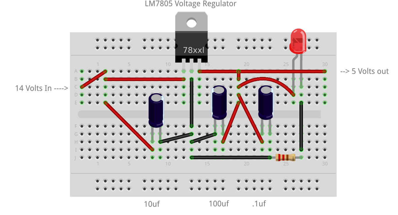
Get the Fritzing code for that circuit image here.

This is what the circuit looks like when built.
I used an RJ11 splitter to attach both the ME-ARC and my arduino at the same time.
The splitter  was connected to the back of the ME-ARC. The RJ11 cable from the inverter was plugged into one side of the splitter and the cable to the arduino was plugged into the other side of the splitter. Wiring that way allows viewing the ME-ARC and checking what it is showing versus what the arduino is showing. This is a good way to check that the code in the arduino is providing the same (accurate) results.
Since the communications from the inverter uses the RS485 protocol, we will use the wiring shown in a previous post which uses the SN75176BP IC for the protocol conversion.
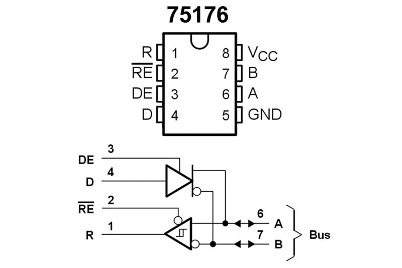 If you haven’t taken the time to read that post, here are the wiring diagrams for the SN75176BP (left) and the complete circuit (below). The diagram shows RS485 communications between two arduinos, however, we can just pretend that one of the arduinos is the inverter. In fact, one of the arduinos was running code to emulate the inverter for testing purposes but I did not mention that in the original post. Now you know. 🙂
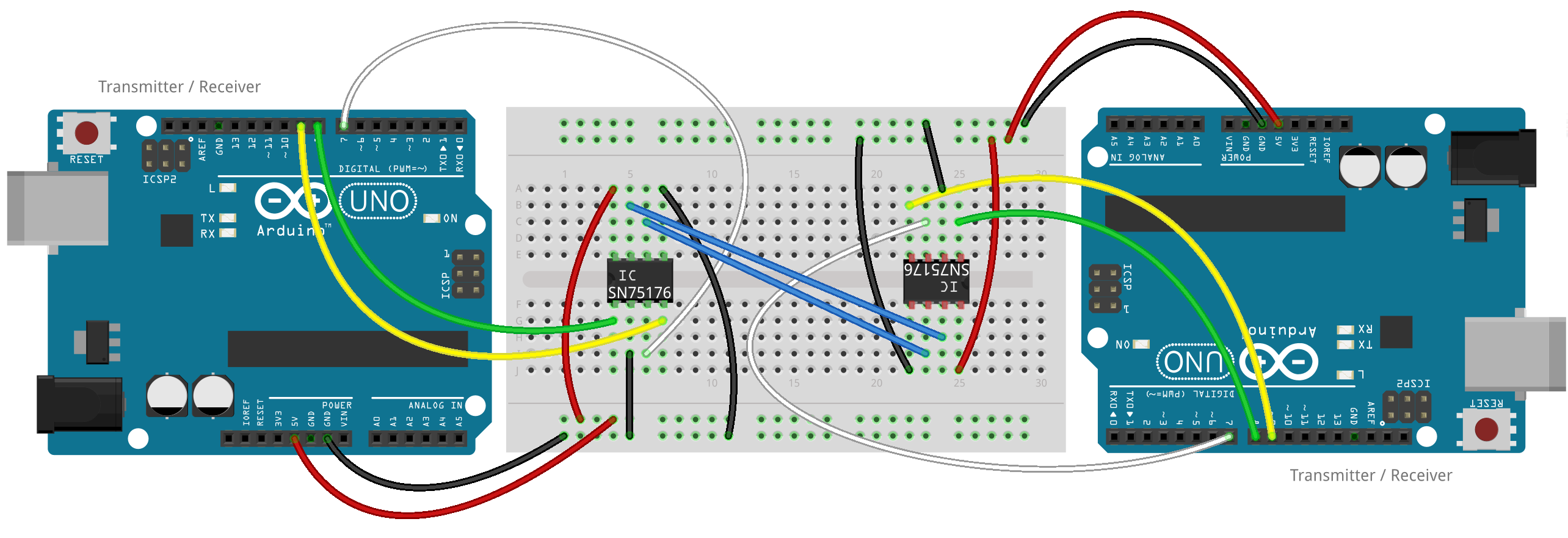
Get the Fritzing code for that diagram here. For connecting just one arduino to the actual inverter, the ‘A’ pin (from the RJ11 connector pin 4) connects to the ‘A’ pin of the SN75176BP and the ‘B’ pin (from the RJ11 connector pin 1) connects to the ‘B’ pin of the SN75176BP.
In hooking up the LCD to the arduino, we will also use the information from a previous post. There we show how to use a shift register IC to minimize the number of pins used to connect the LCD to the arduino.
Now that we have all of the hardware details, we can hook it all up. The RJ11 splitter is connected to the ME-ARC. The RJ11 cable from the inverter is connected to one side of the splitter. The other side of the splitter is connected to the arduino circuit this way:
Pin 1 - 'B' pin of SN75176BP
Pin 2 - 14 Volts to input of the LM7805 circuit
Pin 3 - Ground to Ground of the LM7805 circuit
Pin 4 - 'A' pin of SN75176BP
Here is what it looks like all attached and working:
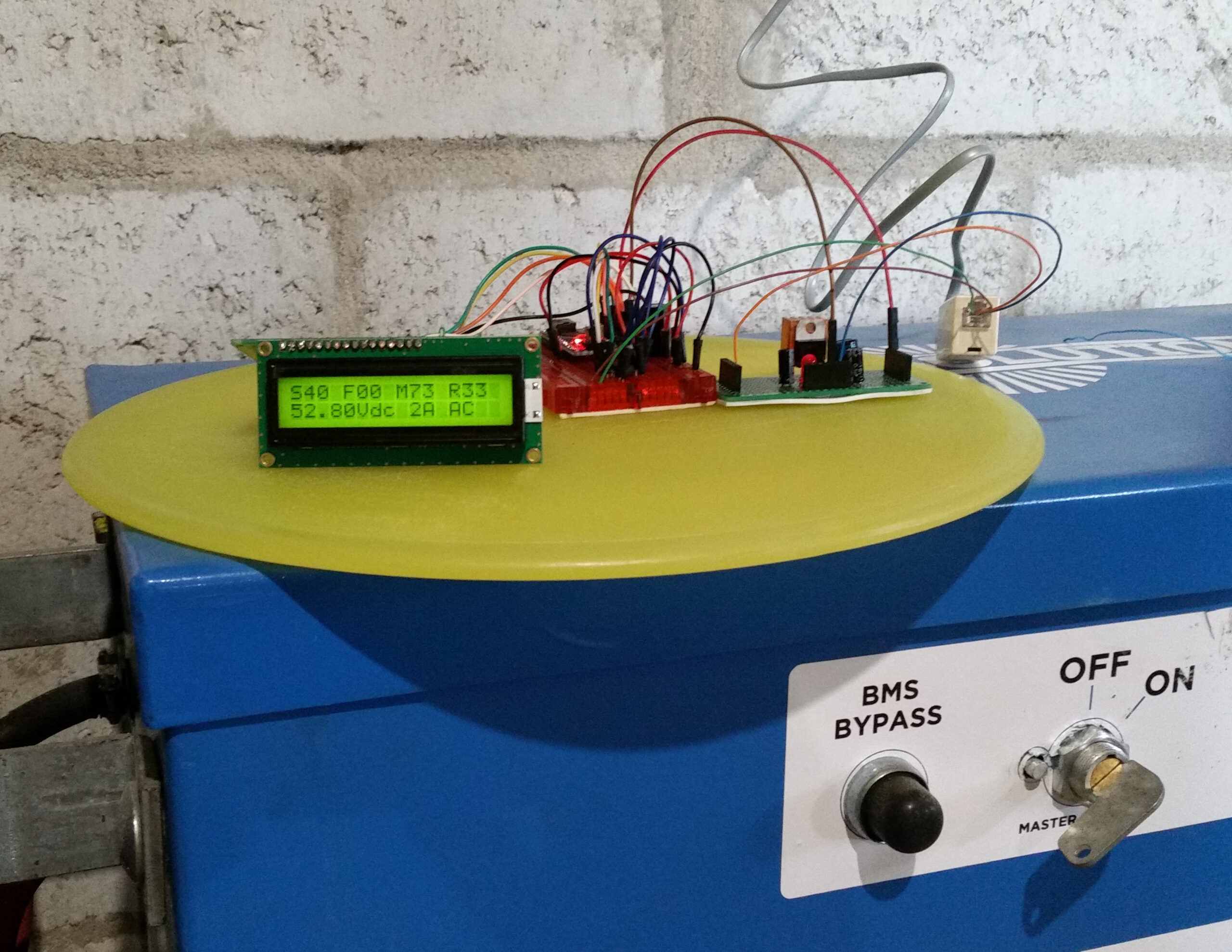
From the picture, you can see the RJ11 cable (on the right) dropped down from the splitter on the ME-ARC. I have an RJ11 female/female connector to the cable and to an RJ11 connector which breaks out the 4 wires connecting to the arduino and the voltage regulator circuits.
You are probably wondering about the output on the LCD? Since the LCD has only 16 characters x 2 lines, it has limited space to display things. The first line has ‘codes’ for what it is displaying:
S40 - Status 40 (inverting)
F00 - Fault (none)
M73 - Inverter Model  (MS4448PAE)
R33 - Revision 33 (Inverter revision)
The 2nd line displays the DC volts and amps being used just like the ‘Meter’ on the ME-ARC. The code in the arduino gets these values from a data packet sent by the inverter every 100 milliseconds. The Magnum Network Communications Protocol document (mentioned earlier) details the communications and values being sent.
Here is the arduino code so you can see how the arduino captures the inverter data, waits for the 100 millisecond ‘gap’ and then decodes and displays the values.
/*
RS485 Communications to a Magnum Inverter
from earl@microcontrollerelectronics.com
*/

#include <SoftwareSerial.h>
#include <LiquidCrystal595.h>

#define MAXBUFFER 512
#define DE 7

LiquidCrystal595 lcd(3,4,5);   // datapin, latchpin, clockpin
SoftwareSerial mySerial(8,9);  // RX, TX

uint32_t last_millis = 0;
uint32_t timer       = 0;
unsigned int bl      = 0;
float    volts       = 0.0;
int      amps        = 0;

unsigned char Buffer[MAXBUFFER+1];

char data[256];
char DcV[10];

void setup() {
//  Serial.begin(19200);
  mySerial.begin(19200);
  pinMode(DE,OUTPUT);
  digitalWrite(DE,LOW);
  lcd.init(3,4,5);
  lcd.setLED2Pin(HIGH);        // Backlight On
  lcd.begin(16,2);             // 16 characters, 2 rows
  lcd.clear();
  lcd.print("No Data yet!");
  last_millis = millis();
}

void loop() {
/*
 if (Serial.available()) {
   digitalWrite(DE,HIGH);
   mySerial.write(Serial.read());
   digitalWrite(DE,LOW);
 }
*/
 while (mySerial.available() > 0) {
  if (bl > MAXBUFFER) bl = 0;
  Buffer[bl] = mySerial.read();
  ++bl;
  last_millis = millis();
 }
 timer = millis() - last_millis;
 if ( (timer > 30) && (bl > 15) ) {
// Left in for Debugging
//   sprintf(data,"%02X%02X%02X%02X%02X%02X%02X%02X",Buffer[0],Buffer[1],Buffer[2],Buffer[3],Buffer[4],Buffer[5],Buffer[6],Buffer[7],Buffer[8]);
   lcd.setCursor(0,0);
   sprintf(data,"S%02X F%02x M%02X R%02X",Buffer[0],Buffer[1],Buffer[14],Buffer[10]);
   lcd.print(data);
   volts = ( ((unsigned char)(Buffer[2]) * 256) + (unsigned char)(Buffer[3]) ) / 10.0;
   dtostrf(volts,5,2,DcV);
   amps = ((unsigned char)(Buffer[4]) * 256) + (unsigned char)(Buffer[5]);
   sprintf(data,"%s5Vdc %3dA",DcV,amps);
   lcd.setCursor(0,1);
   lcd.print(data);
   bl = 0;
 }
}
One serial port is used for communications to the inverter and another is used to optionally communicate with a PC and get commands to send to the inverter. Note: The code for transmitting data to the inverter is there but commented out. I am using the Software Serial library (to emulate an additional serial port) because the Arduino Nano I am using for this project only has one serial port. The other library (LiquidCrystal595) is needed to control the LCD with only 3 pins. Make sure, if you use that library, to patch it according to the comments in my post about it mentioned above and referenced again here.
Since the inverter sends a data packet every 100 milliseconds, we can check for that ‘gap’ (no data being sent) and know that we have a complete packet. However, since it will take some time to run the code to display on the LCD we need to pick a ‘safe’ value for checking that timing. You will notice in the code:
timer = millis() - last_millis;
if ( (timer > 30) && (bl > 15) ) {
the timer holds the number of milliseconds since the last input byte from the inverter. I chose a ‘safe’ value of 30 (milliseconds) which should give enough time to display on the LCD and get back to checking for inverter data.
The next step would be to test sending data to the inverter as does the actual ME-ARC remote. Only then would we have something to be able to totally replace the ME-ARC.
So now you can see that there are ‘building blocks’ (so to speak) in my posts which used together can produce something practical, Solar Power System Monitoring with an Arduino.
3 comments
Thank you for your post.
Very interesting and quite informative.
Great engineering, if you will.
in my case first i need to send a command to inverter then it will return some energy parameters
what changes should i make for that reason in above program
Author
You might notice that I have commented out the code where I had a Serial Port connected. Right after the loop() you should see these commands commented out:
digitalWrite(DE,HIGH);
mySerial.write(Serial.read());
digitalWrite(DE,LOW);
That is code to send things out to the Inverter that come from the Serial port. If you wanted to send something to the inverter that you code in the program, use something like this:
//Set DE to HIGH
digitalWrite(DE,HIGH);
//Send command to the inverter
mySerial.write(“data to send”);
Set DE to LOW
digitalWrite(DE,LOW);
Where “data to send” is the string (command) to send. Be very careful what you send if there is any possibility to ruin something in your inverter setup.
Earl