
If you read my last post on Solar Power System Monitoring with an Arduino you might be wondering if that circuit could be enhanced a bit. Say, change the LCD to an OLED and add wireless (WEB server) capability?
I was not happy to have to go out and look at the device when I wanted to see the info. So I did enhance it a bit. I changed the LCD to an OLED for more info in case I did happen to be where the device is and I added a wireless module (an ESP8266). The wireless module has a WEB server so I can just connect wireless via a browser and see the info.
Since the ESP8266 needs 3 Volts, I also changed the ‘arduino’ I was using. I switched to an STM32F103C8T6 (BluePill) since it can take 5 Volts and output 3 Volts. This new circuit still uses the LM7805 voltage regulator to take the 14 Volt input and then output 5 Volts. It also keeps the SN75176BP for the RS485 protocol conversion. If you have not read the previous post, you can find more details there on those components.
Here is what the circuit wiring looks like:
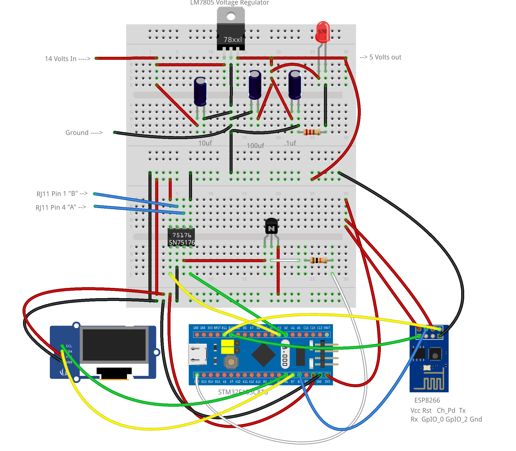
You can get the Fritzing code for this circuit here.
Here is what the circuit looks like (top and front side view):

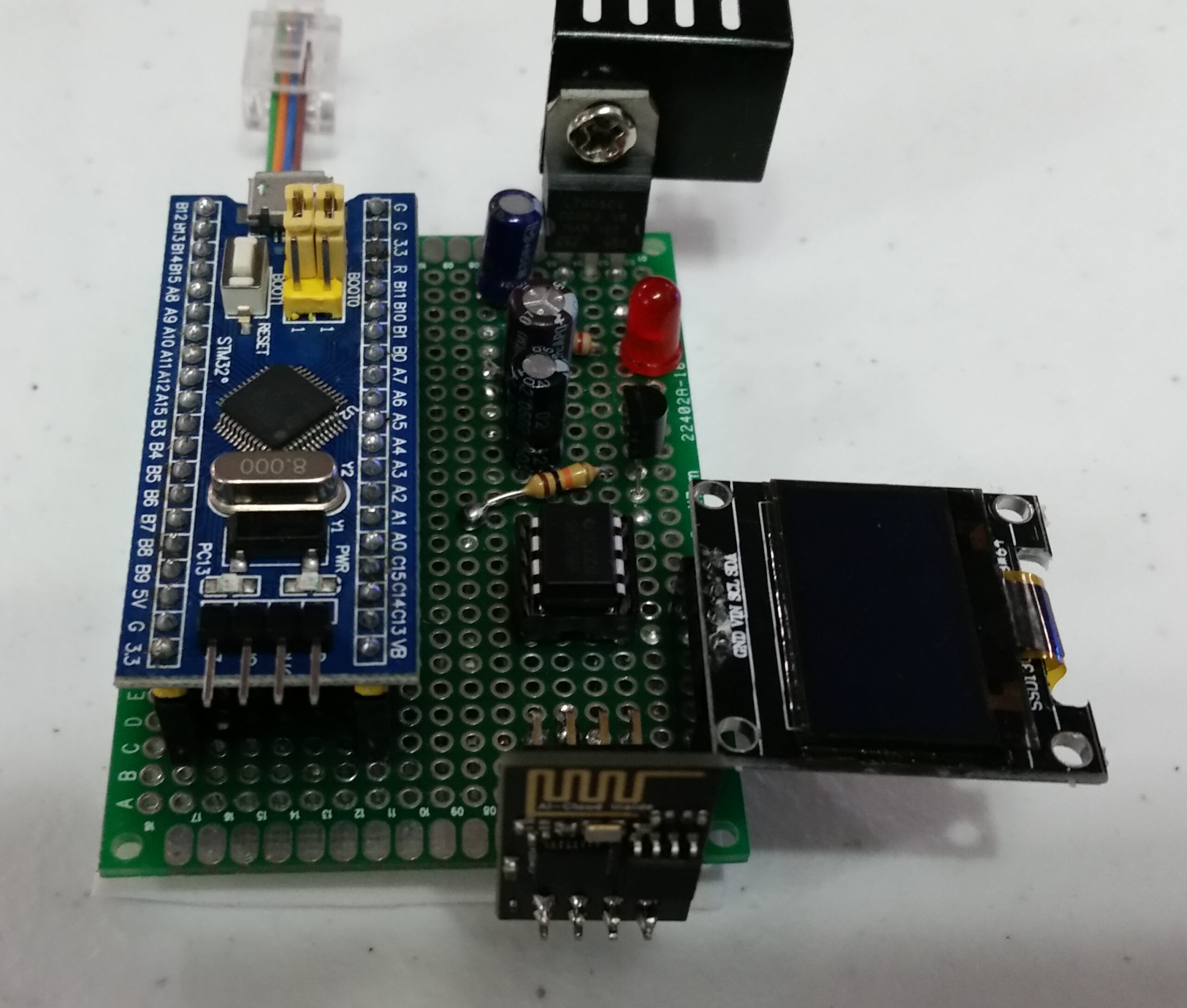
The left side has the STM32F103C8T6 and the RJ11 connector. The right side has the ESP8266, the OLED, the SN75176BP and the LM7805. The LM7805 has a heat sink on it since it gets a bit hot. The STM32F103C8T6, ESP8266, OLED and SN75176BP are all in sockets for easy (re)placement. This circuit has all the ‘messy’ wiring and soldering on the bottom (hidden from view). In my previous post I still had all the components on a breadboard.
Here is the code to load into the STM32F103C8T6 (using the Arduino IDE):
/*

    PA9/PA10  Serial
    PB10/PB11 Serial2
    PA2/PA3   Serial1
    I2C1 SDA PB7
    I2C1 SCL PB6

               +-----------------[USB]-----------------+
  [SS2|PB12]   | [31]                            [Gnd] |
  [SCK2|PB13]  | [30]                  +---+     [Gnd] |
  [MISO2|PB14] | [29]    +-----+       |0 0|     [3V3] |
  [MOSI2|PB15] | [28]    |Reset|       |x x|   [Reset] |
       [PA8]   | [27]    +-----+       |1 1|      [ 0] | [PB11|SDA2|RX3]
   [TX1|PA9]   | [26]                  +---+      [ 1] | [PB10|SCL2|TX3]
  [RX1|PA10]   | [25]                   ^ ^       [33] | [PB1]
  [USB-|PA11]  | [24]            Boot1--+ |       [ 3] | [PB0|A0]
  [USB+|PA12]  | [23]            Boot0----+       [ 4] | [PA7|A1|MOSI1]
      [PA15]   | [20]                             [ 5] | [PA6|A2|MISO1]
       [PB3]   | [19]        +-----------+        [ 6] | [PA5|A3|SCK1]
       [PB4]   | [18]        | STM32F103 |        [ 7] | [PA4|A4|SS1]
       [PB5]   | [17]        | Blue Pill |        [ 8] | [PA3|A5|RX2]
  [SCL1|PB6]   | [16]        +-----------+        [ 9] | [PA2|A6|TX2]
  [SDA1|PB7]   | [15]                             [10] | [PA1|A7]
       [PB8]   | [32]                             [11] | [PA0|A8]
       [PB9]   | [PB9]                            [12] | [PC15]
               | [5V]      +---------------+      [13] | [PC14]
               | [Gnd]     |    ST-Link    |      [14] | [PC13|LED]
               | [3V3]     |3V3 DIO CLK GND|     [Vbat]|
               +-------------+---+---+---+-------------+
                             |   |   |   |
*/

#include <Adafruit_GFX.h>
#include <Adafruit_SSD1306_STM32.h>

#define OLED_RESET PB4
Adafruit_SSD1306 display(OLED_RESET);

String sbuffer = "";
char connectionId;
#define MAXBUFFER 512
#define DE PB12
#define ESP8266_RESET PB8

uint32_t last_millis = 0;
uint32_t timer       = 0;
unsigned int bl      = 0;
float    volts       = 0.0;
int      amps        = 0;

unsigned char Buffer[MAXBUFFER + 1];
unsigned char SBuffer[MAXBUFFER + 1];

char data[256];
char DcV[10];

// Serial  -> host PC
// Serial1 -> RS485 SN75176
// Serial2 -> ESP8266

void setup() {
  display.begin(SSD1306_SWITCHCAPVCC, 0x3C);  // initialize with the I2C addr 0x3D (for the 128x64)
  display.display();
  Serial.begin(115200);
  Serial2.begin(115200);
  Serial1.begin(19200);
  pinMode(DE, OUTPUT);
  digitalWrite(DE, LOW);
  display.clearDisplay();
  display.display();
  display.setTextSize(1);
  display.setTextColor(WHITE);
  display.setCursor(0, 0);
  display.println("Setting up ESP8266..");
  display.display();
  Serial.println("Setting up ESP8266...");
  init_server();
  Serial.println("Setup Done!");
  display.clearDisplay();
  display.display();
  display.setTextSize(1);
  display.setTextColor(WHITE);
  display.setCursor(0, 0);
  display.println("Setup Done!");
  display.display();
  last_millis = millis();
}

void init_server() {
  sendData("AT+RST\r\n", 5000, (String)"jump to run", 1);
  sendData("AT+RESTORE\r\n", 5000, (String)"ready", 1);
  sendData("AT+GMR\r\n", 5000, (String)"OK", 1);
  sendData("AT+CWMODE=2\r\n", 5000, (String)"OK", 1);
  String cmd = "AT+CWSAP=\"ESP8266\",\"\",6,0\r\n";
  sendData(cmd, 5000, (String)"OK", 1);
  sendData("AT+CIFSR\r\n", 5000, (String)"OK", 1);
  sendData("AT+CIPMUX=1\r\n", 5000, (String)"OK", 1);
  sendData("AT+CIPSERVER=1,80\r\n", 5000, (String)"OK", 1);
}

void get_serial_data() {
  while (Serial1.available() > 0) {
    if (bl > MAXBUFFER) bl = 0;
    Buffer[bl] = Serial1.read();
    ++bl;
    last_millis = millis();
  }
  while (Serial2.available() > 0) {
    char c = Serial2.read();
    sbuffer.concat(c);
    Serial.write(c);
  }
}

void loop() {
  get_serial_data();

  /*
    if (Serial.available()) {
      digitalWrite(DE,HIGH);
      Serial1.write(Serial.read());
      digitalWrite(DE,LOW);
    }
  */

  timer = millis() - last_millis;

  if ( (timer > 30) && (bl > 15) ) {
    for (int i = 0; i < bl; ++i) SBuffer[i] = Buffer[i];
    bl = 0;
    display.clearDisplay();
    display.display();
    display.setTextSize(2);
    display.setTextColor(WHITE);
    display.setCursor(0, 0);
    display.println("Magnum Inverter");
    display.setTextSize(1);
    // Left in for Debugging
    //   sprintf(data,"%02X%02X%02X%02X%02X%02X%02X%02X",SBuffer[0],SBuffer[1],SBuffer[2],SBuffer[3],SBuffer[4],SBuffer[5],SBuffer[6],SBuffer[7],SBuffer[8]);
    sprintf(data, "S%02X F%02x M%02X R%02X", SBuffer[0], SBuffer[1], SBuffer[14], SBuffer[10]);
    display.println(data);
    volts = ( ((unsigned char)(SBuffer[2]) * 256) + (unsigned char)(SBuffer[3]) ) / 10.0;
    dtostrf(volts, 5, 2, DcV);
    amps = ((unsigned char)(SBuffer[4]) * 256) + (unsigned char)(SBuffer[5]);
    sprintf(data, "%s5Vdc %3dA", DcV, amps);
    display.println(data);
    display.display();
  }

  if (sbuffer.indexOf("busy") != -1) init_server();

  if (sbuffer.indexOf("+IPD,") != -1) {
    timer = millis() + 500;
    while (millis() < timer) get_serial_data();
    int pos = sbuffer.indexOf(",CONNECT");
    if (pos != -1) pos -= 1;
    if (sbuffer[pos] == 0x0d) connectionId = sbuffer[pos + 2];
    else                      connectionId = sbuffer[pos];
    Serial.println(connectionId, HEX);
    String webpage = F("<!DOCTYPE HTML>\n<html>\n<body>\n<H1>Magnum Inverter</H1>\n");

    // Left in for Debugging
    //   sprintf(data,"%02X%02X%02X%02X%02X%02X%02X%02X",SBuffer[0],SBuffer[1],SBuffer[2],SBuffer[3],SBuffer[4],SBuffer[5],SBuffer[6],SBuffer[7],SBuffer[8]);

    sprintf(data, "S%02X F%02x M%02X R%02X", SBuffer[0], SBuffer[1], SBuffer[14], SBuffer[10]);
    webpage += "<H2>";
    webpage += data;
    webpage += "</H2>";
    volts = ( ((unsigned char)(SBuffer[2]) * 256) + (unsigned char)(SBuffer[3]) ) / 10.0;
    dtostrf(volts, 5, 2, DcV);
    amps = ((unsigned char)(SBuffer[4]) * 256) + (unsigned char)(SBuffer[5]);
    sprintf(data, "%s5Vdc %3dA", DcV, amps);
    webpage += "<H2>";
    webpage += data;
    webpage += "</H2>";
    webpage += F("<script>setTimeout(function(){window.location.reload(1);},5000);</script>\n");
    webpage += F("</body>\n</html>");
    String cipSend = "AT+CIPSEND=";
    cipSend += connectionId;
    cipSend += ",";
    cipSend += webpage.length();
    cipSend += "\r\n";
    sendData(cipSend, 2000, (String)"OK", 1);
    sendData(webpage, 2000, (String)"SEND OK", 1);
    String closeCommand = "AT+CIPCLOSE=";
    closeCommand += connectionId;
    closeCommand += "\r\n";
    sendData(closeCommand, 2000, (String)"OK", 1);
  }
}

void sendData(String command, const int timeout, String msg, boolean flag) {
  Serial2.print(command);
  display.clearDisplay();
  display.display();
  display.setTextSize(1);
  display.setTextColor(WHITE);
  display.setCursor(0, 0);
  display.println(command);
  display.display();
  long int time = millis() + timeout;
  while (time > millis()) {
    get_serial_data();
    if (sbuffer.indexOf(msg) != -1) break;
  }
  if (sbuffer.indexOf(msg) == -1) {
    long int time1 = millis() + 500;
    while ( time1 > millis()) {
      get_serial_data();
      if (sbuffer.indexOf(msg) != -1) break;
    }
  }
  get_serial_data();
  display.println(sbuffer);
  display.display();
  if (flag) sbuffer = "";
}
I am using the Adafruit GFX and SSD1306 libraries to control the OLED. The ESP8266 is just connected via a serial connection and sent commands to set it up as an access point and WEB server.
The wireless access point name is just set to ESP8266. You can change it to anything you want. The IP address is 192.168.4.1, so just go to that IP address in a browser after connecting wirelessly. The WEB page will refresh every 5 seconds.
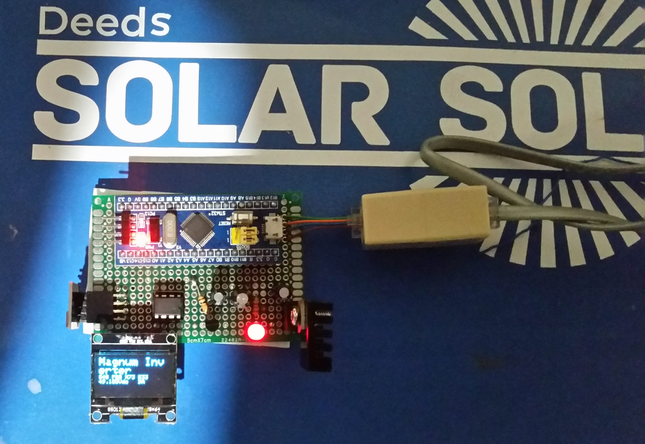
My next step is to enhance the code to display more info as it still only outputs the codes like the LCD version does. Here is a picture (photography is not my forte) of the device on top of one of my Lithium Batteries (from Deeds Solar Solutions).
Recent Comments