
This is a short post which shows how to create a wireless WEB server on an ESP8266. It uses a microcontroller, in this case an STM32F103C8T6 (BluePill ) to send commands and control the ESP8266
Here is what the wiring looks like:.
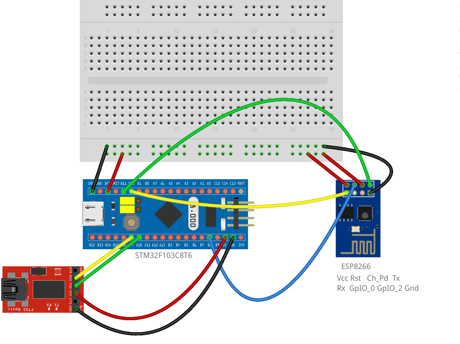
You can get the Fritzing code for this image here.
Here is the Arduino IDE source code to load into the STM32F103C8T6 (BluePill) to create a Wireless WEB Server on an ESP8266:
/*

 From: earl@microcontrollerelectronics.com

 *  PA9/PA10  Serial
 *  PA2/PA3   Serial1
 *  PB10/PB11 Serial2
 *  I2C1 SDA PB7
 *  I2C1 SCL PB6
 *
 *            +-----------------[USB]-----------------+
  [SS2|PB12] | [31]                            [Gnd] |
 [SCK2|PB13] | [30]                  +---+     [Gnd] |
[MISO2|PB14] | [29]    +-----+       |0 0|     [3V3] |
[MOSI2|PB15] | [28]    |Reset|       |x x|   [Reset] |
       [PA8] | [27]    +-----+       |1 1|      [ 0] | [PB11|SDA2|RX3]
   [TX1|PA9] | [26]                  +---+      [ 1] | [PB10|SCL2|TX3]
  [RX1|PA10] | [25]                   ^ ^       [33] | [PB1]
 [USB-|PA11] | [24]            Boot1--+ |       [ 3] | [PB0|A0]
 [USB+|PA12] | [23]            Boot0----+       [ 4] | [PA7|A1|MOSI1]
      [PA15] | [20]                             [ 5] | [PA6|A2|MISO1]
       [PB3] | [19]        +-----------+        [ 6] | [PA5|A3|SCK1]
       [PB4] | [18]        | STM32F103 |        [ 7] | [PA4|A4|SS1]
       [PB5] | [17]        | Blue Pill |        [ 8] | [PA3|A5|RX2]
  [SCL1|PB6] | [16]        +-----------+        [ 9] | [PA2|A6|TX2]
  [SDA1|PB7] | [15]                             [10] | [PA1|A7]
       [PB8] | [32]                             [11] | [PA0|A8]
       [PB9] | [PB9]                            [12] | [PC15]
             | [5V]      +---------------+      [13] | [PC14]
             | [Gnd]     |    ST-Link    |      [14] | [PC13|LED]
             | [3V3]     |3V3 DIO CLK GND|     [Vbat]|
             +-------------+---+---+---+-------------+
                           |   |   |   |

*/

String sbuffer = "";
char connectionId;
uint32_t timer = 0;

#define ESP8266_RST PB8

void setup() {
  pinMode(ESP8266_RST,OUTPUT);
  Serial.begin(115200);
  Serial2.begin(115200);
  init_server();
}

void init_server() {
  digitalWrite(ESP8266_RST,LOW);
  delay(100);
  digitalWrite(ESP8266_RST,HIGH);
  sendData("AT+RST\r\n",5000,(String)"ready",1);
  sendData("AT+GMR\r\n",5000,(String)"OK",1);
  sendData("AT+CWMODE=2\r\n",5000,(String)"OK",1);
  String cmd = "AT+CWSAP=\"ESP8266\",\"\",6,0\r\n";
  sendData(cmd,5000,(String)"OK",1);
  sendData("AT+CIFSR\r\n",5000,(String)"OK",1);
  sendData("AT+CIPMUX=1\r\n",5000,(String)"OK",1);
  sendData("AT+CIPSERVER=1,80\r\n",5000,(String)"OK",1);
}

void get_serial_data() {
  while(Serial2.available()) {
    char c = Serial2.read();
    sbuffer.concat(c);
    Serial.write(c);
  }
}

void loop() {
  get_serial_data();

  if (sbuffer.indexOf("busy") != -1) init_server();
  if (sbuffer.indexOf("ERROR") != -1) init_server();

  if (sbuffer.indexOf("+IPD,") != -1) {
    timer = millis() + 1000;
    while (millis() < timer) get_serial_data();
    int pos = sbuffer.indexOf(",CONNECT");
    if (pos != -1) pos -= 1;
    if (sbuffer[pos] == 0x0d) connectionId = sbuffer[pos+2];
    else                      connectionId = sbuffer[pos];
    Serial.println(connectionId,HEX);
    String webpage = "<!DOCTYPE HTML>\n<html>\n<body>\n<h1>Hello World!</h1>\n";
    webpage += "<script>setTimeout(function(){window.location.reload(1);},5000);</script>\n";
    webpage += "</body>\n</html>";
    String cipSend = "AT+CIPSEND=";
    cipSend += connectionId;
    cipSend += ",";
    cipSend += webpage.length();
    cipSend += "\r\n";
    sendData(cipSend,2000,(String)"OK",1);
    sendData(webpage,2000,(String)"SEND OK",1);
    String closeCommand = "AT+CIPCLOSE=";
    closeCommand += connectionId;
    closeCommand += "\r\n";
    sendData(closeCommand,2000,(String)"OK",1);
  }
}

void sendData(String command, const int timeout, String msg, boolean flag) {
  Serial.println(command);
  Serial2.print(command);
  long int time = millis() + timeout;
  while(time > millis()) {
    get_serial_data();
    if (sbuffer.indexOf(msg) != -1) break;
  }
  if (sbuffer.indexOf(msg) == -1) {
    long int time1 = millis() + 500;
    while( time1 > millis()) {
      get_serial_data();
      if (sbuffer.indexOf(msg) != -1) break;
    }
  }
  get_serial_data();
  if (flag) sbuffer = "";
}
If you open the serial monitor on the Arduino IDE while the code is running you will see the commands being sent to the ESP8266 and its response. You can also watch what comes to its WEB site and what it sends out in return. This can be an interesting learning experience for the beginner.
This is a simple project to make but can be the start of a bigger project or added to another circuit to add wireless capabilities.
2 comments
Hi there, thanks for sharing this nice post.
How can I control GPIO`s of stm32f103c8t6 with ESP8266 via web server?
Author
You’ll need to change the WEB page sent to allow changes to the pin status and then capture that page when it is submitted back. The capture of the data coming back is there already in the code (get_serial_data function).
The WEB page sent back can be parsed to check for what you want done in the get_serial_data function.
Sorry I don’t have any examples for specifically parsing the data coming back.