There are various ways for two Arduinos to communicate information. A common way is serially via RS232. However, RS232 has distance limitations. If there is a need to serially communication over a longer distance consider using RS485 instead. A couple of MAX485 ICs can facilitate RS485 Arduino communications over that longer distance.
Two MAX485 ICs connected together will take RS232 signals and perform the voltage level conversions required to turn them into RS485 signals and back again to RS232 signals. That will allow two Arduinos to communicate serially over a longer distance.
This chart shows the specific pin functions on the MAX485:
      MAX485
   +----U-----+
RO | 1      8 | Vcc
RE | 2      7 | B
DE | 3      6 | A
DI | 4      5 | Gnd
   +----------+

RO  - Receiver out
RE  - Receiver enable (enabled when this pin is LOW)
DE  - Driver   enable (enabled when this pin is HIGH)
DI  - Driver   in (the transmitter pin)
GND - Ground (0V)
A   - Connect to pin A of the other 485 IC
B   - Connect to pin B of the other 485 IC
Vcc - Power (Vcc)
Here is how to connect the two Arduinos using two MAX485 ICs:
Get the Fritzing source HERE. 5V is used in this simple demonstration. For longer distances a higher voltage will be needed to power the MAX485. Also the BAUD rate will need to be adjusted (the longer the distance, the slower the speed).
This is the source code for the Transmitter:
/* Arduino Transmitter */
#define LED_PIN 13
#include <SoftwareSerial.h>

SoftwareSerial mySerial(10, 11);
// RX on digital pin 10
// TX on digital pin 11

int i = 0;
void setup() {
  Serial.begin(57600);
  mySerial.begin(57600);
}

void loop() {
  Serial.println(i);
  mySerial.println(i);
  digitalWrite(LED_PIN, !digitalRead(LED_PIN));
  delay(1000);
  i++;
}
This is the source code for the Receiver:
/* Arduino Receiver */

#include <SoftwareSerial.h>

SoftwareSerial mySerial(10, 11); // RX, TX

void setup() {
  Serial.begin(57600);
  mySerial.begin(57600);
}

void loop() {
  if (mySerial.available()) {
    Serial.write(mySerial.read());
  }
/*
  if (Serial.available()) {
    mySerial.write(Serial.read());
  }
*/
}
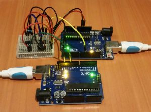
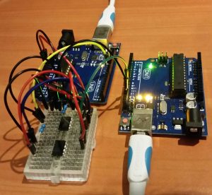
Here is what it looks like (messy wiring and all):


4 comments
Skip to comment form
I am writing from japan.
I have a question.
I don’t understand the orientation of the MAX485.
The picture don’t connect to pin A and B of the other 485 IC by blue line.
I’m not good at English.
I’m happy to answer.
Author
Notice: The MAX485 ICs are not oriented the same on the breadboard. The MAX485 on the left has pin 1 on the bottom left. The MAX485 on the right has pin 1 on the top right.
On your Fritzing diagram it appears that;
– Left hand UNO, missing RX wire (Pin 10) to the MAX485 chip
– Right hand UNO, missing TX wire (Pin 11) to the MAX485 chip
Author
Yes.. they are missing. The one is labeled sender and the other is labeled receiver. I only wanted to send one way.. However, you can add more code and the other wires to easily accomplish two way communications…
Note that the MAX485 does not do full duplex. See my other (post https://microcontrollerelectronics.com/sn75176-rs485-communications-between-two-arduinos/) which details the SN75176 IC which works better than the MAX485. It has all the wiring ..