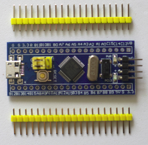
How good are you at soldering? Here is the STM32F103C8T6 microcontroller board that I use and have to solder all of the pins.
Sometimes when I solder pins to the board, the connection looks OK and even tests OK with continuity on a multimeter. However, the solder connections even though they pass those two tests sometimes don’t fully connect the pin to the board. More information about common soldering problems can be found here.
I came up with a way to better test those connections. It is an Arduino sketch that tests all of the pins to make sure they work when connected to an LED.
Here is the STM32F103C8T6 pin tester to check your soldering sketch:
// From earl@microcontrollerelectronics.com
/*
             +-----------------[USB]-----------------+
  [SS2|PB12] | [31]                            [Gnd] |
 [SCK2|PB13] | [30]                  +---+     [Gnd] |
[MISO2|PB14] | [29]    +-----+       |0 0|     [3V3] |
[MOSI2|PB15] | [28]    |Reset|       |x x|   [Reset] |
       [PA8] | [27]    +-----+       |1 1|      [ 0] | [PB11|SDA2|RX3]
   [TX1|PA9] | [26]                  +---+      [ 1] | [PB10|SCL2|TX3]
  [RX1|PA10] | [25]                   ^ ^       [33] | [PB1]
 [USB-|PA11] | [24]            Boot1--+ |       [ 3] | [PB0|A0]
 [USB+|PA12] | [23]            Boot0----+       [ 4] | [PA7|A1|MOSI1]
      [PA15] | [20]                             [ 5] | [PA6|A2|MISO1]
       [PB3] | [19]        +-----------+        [ 6] | [PA5|A3|SCK1]
       [PB4] | [18]        | STM32F103 |        [ 7] | [PA4|A4|SS1]
       [PB5] | [17]        | Blue Pill |        [ 8] | [PA3|A5|RX2]
  [SCL1|PB6] | [16]        +-----------+        [ 9] | [PA2|A6|TX2]
  [SDA1|PB7] | [15]                             [10] | [PA1|A7]
       [PB8] | [32]                             [11] | [PA0|A8]
       [PB9] | [PB9]                            [12] | [PC15]
             | [5V]      +---------------+      [13] | [PC14]
             | [Gnd]     |    ST-Link    |      [14] | [PC13|LED]
             | [3V3]     |3V3 DIO CLK GND|     [Vbat]|
             +-------------+---+---+---+-------------+
                           |   |   |   |

PA9  TX / PA10 RX Serial Upload Serial
PA2  TX / PA3  RX Serial1
PB10 TX / PB11 RX Serial2

*/

const uint8_t pins[] = {
  PB12,PB13,PB14,PB15,PA8,PA9,PA10,PA11,PA12,PA15,PB3,PB4,PB5,PB6,PB7,PB8,PB9,
  PB11,PB10,PB1,PB0,PA7,PA6,PA5,PA4,PA3,PA2,PA1,PA0,PC15,PC14,PC13
};

#define NUMPINS (sizeof(pins) / sizeof(pins[0]))

void setup() {
  for(int i=0;i<NUMPINS;++i) pinMode(pins[i],OUTPUT);
}

void loop() {
  for(int i=0;i<NUMPINS;++i) {
    digitalWrite(pins[i],!digitalRead(pins[i]));
    delay(100);
  }
}
The sketch uses an array called ‘pins’ with a list of all the STM32F103C8T6 pin names. The setup code sets all the pins to output and the main loop just toggles the pins with a 100 millisecond delay. This makes sure that the LED will toggle ON/OFF if the connection is working properly.
Make sure to use the STM32F103C8T6 Arduino Core from here as it supports using all the pins as output and testing with an LED.
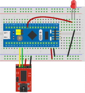
Once you load it into the STM32F103C8T6, then just make sure it has power and ground and connect an LED to each pin in succession and make sure it lights up. If it doesn’t, then you know it is a bad connection. This is also a way to test any connection wires that need testing. Sometimes they are ‘bad’ too, due to defects in manufacturing or just usage.


Recent Comments