I have a new version of my DIY Arduino UNO. It is somewhat different than the old one that I have written about before (HERE). I moved some components around on the board, added the user LED and moved all the wiring to the bottom of the board.
Here is a picture of what it looks like:
If you’ve followed along in my blog posts, you will have seen other pictures of it in use. Additionally, I have added an optional 40 (10 x 4) pin breadboard which makes it quite handy to test any add on circuitry. I also added jumpers to connect / disconnect the LEDs (to conserver power). I printed ‘stickers’ for the Atmega328 and used silicon to stick them on. Get them here. The sticker makes it easy to tell which pin is which.Here are pictures of the top and bottom views of one:
The bottom view was taken before all the wires (necessary to complete the connections) were soldered on. This updated DIY Arduino UNO features:
6 pin male header (90 degrees) to connect an FTDI USB to Serial Converter
14 pin female headers along the socket to easily connect to the microcontroller pins
4 pin male header (shown on left) for extra +5V connections
4 pin male header (shown on right) for extra Ground connections
push button reset switch
red power LED
green user LED (attached to digital pin 13)
jumper(s) to connect / disconnect LEDs
40 pin (10x4) protoboard (breadboard)
The parts list for my updated DIY Arduino UNO is very basic:
Qty             Description
 1   5x7cm laminated fiber board - perforated
 1   28 pin DIP base - socket for Atmega328P-PU
 1   28 pin Atmega328P-PU microcontroller
 2   4 pin male headers (one for ground and one for power)
 1   6 pin male header 90 degrees - for connection to the FTDI USB Converter
 1   10uf capacitor
 3   .1uf capacitor
 1   16Mhz clock crystal
 2   22pf capacitor
 1   push button for reset
 2   220 Ohm resistor
 1   10K Ohm resistor
 1   5mm green LED - user
 1   5mm red LED - power
 2   2 pin jumper for LEDs
 4   10 pin female header (to create breadboard)
 2   14 pin female header (one on each side of socket base)
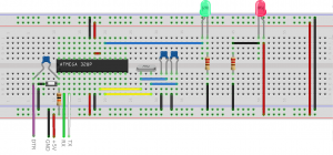
Even though the layout has changed, how things are connected has remained the same. View the larger graphic by clicking the image below which shows the basic connections. (Get the fritzing source .fzz HERE)

![DIY Arduino [Top View]](https://microcontrollerelectronics.com/wp-content/uploads/2017/01/DIY_Arduino_Top_Label-300x229.png)
![DIY Arduino [Top View]](https://microcontrollerelectronics.com/wp-content/uploads/2017/01/DIY_Arduino_Top-300x246.png)
![DIY Arduino [Bottom View]](https://microcontrollerelectronics.com/wp-content/uploads/2017/01/DIY_Arduino_Bottom-300x243.png)

Recent Comments