
Your car is full of electronic devices. In fact, General Motors is one of the largest computer manufacturers due to its need of microcomputers in cars that it makes. If you have an interest in what goes on with your cars’ electronics, you might want to invest some time hacking your car with an Arduino and a CAN BUS Module.
Quoting from the CAN BUS Wikipedia article:
‘A Controller Area Network (CAN bus) is a vehicle bus standard designed to allow microcontrollers and devices to communicate with each other in applications without a host computer. It is a message-based protocol, designed originally for multiplex electrical wiring within automobiles, but is also used in many other contexts.’
A modern car has many ECUs (or Electronic Control Units). These ‘computers’ send and receive information over the cars’ CAN BUS. De-coding that information can give you a wealth of information about the workings of your car.
The CAN BUS on your vehicle can be accessed from the OBD II connector. I wrote about OBD II and diagnosing car problems in an earlier post here. If you are wondering if your car has an OBD II port, it probably does. All cars and light trucks built and sold in the United States after January 1, 1996 were required to be OBD II equipped.
The OBD II connector looks like this:
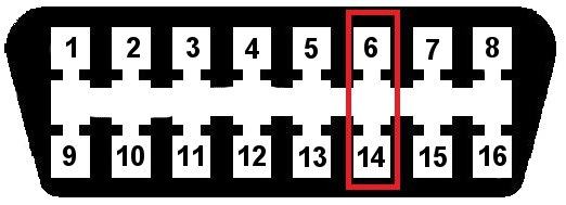
| PIN | DESCRIPTION | PIN | DESCRIPTION |
|---|---|---|---|
| 1 | Vendor Option | 9 | Vendor Option |
| 2 | J1850 Bus + | 10 | J1850 Bus |
| 3 | Vendor Option | 11 | Vendor Option |
| 4 | Chassis Ground | 12 | Vendor Option |
| 5 | Signal Ground | 13 | Vendor Option |
| 6 | CAN (J-2234) High | 14 | CAN (J-2234) Low |
| 7 | ISO 9141-2 K-Line | 15 | ISO 9141-2 Low |
| 8 | Vendor Option | 16 | Battery Power |
Note: Pins 6 and 14 are specifically for the CAN BUS.
The CAN BUS module that I am using looks like this:
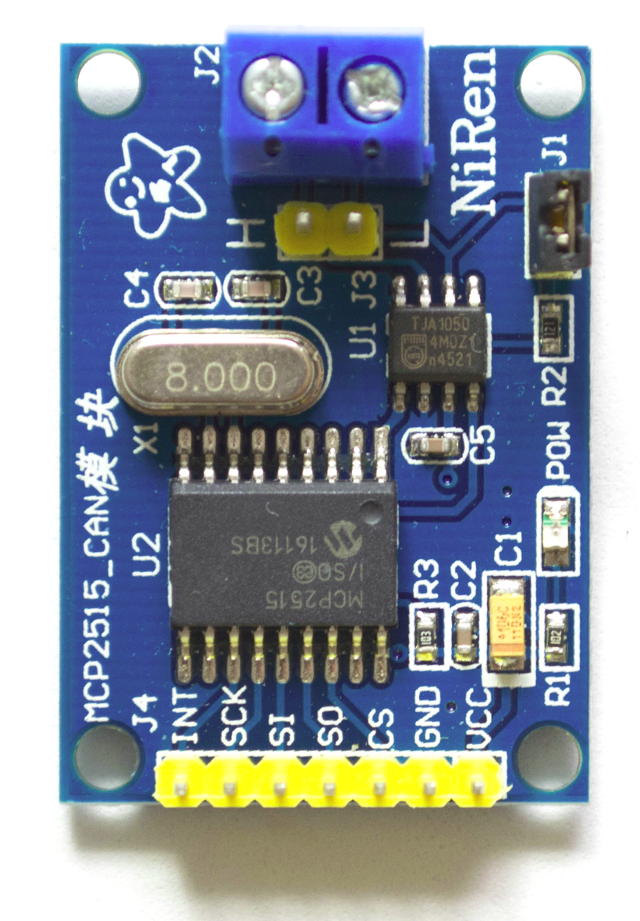
The module has a seven pin connector for attachment to the Arduino . Two pins are used for +5V (power) and GND. The other five (MISO, MOSI, CS, SCK, INT) are for the SPI interface.. The J1 connector is a jumper for 120Ohm termination of the bus. (I have that jumper connected on both modules in my test environment shown below.) The CAN BUS is connected to the module either by the screw terminals or the two pin header behind the screw terminals. Note that one is labeled H for High and the other is L for Low.
Before hacking your car with an Arduino and a CAN BUS module, you may want to do what I did. I used two modules connected together to form a two node test CAN BUS network. That setup looked like this:
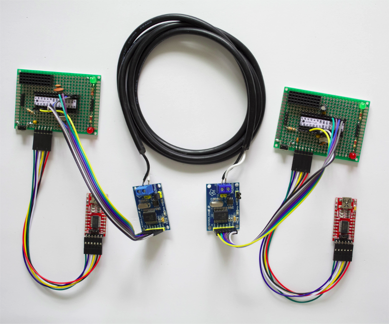
Basically, a double wire connects the CAN BUS High/Low connections on the module which is wired (SPI interface) to the Arduino. Each DIY Arduino has an FTDI USB to Serial connection to the Laptop/Phone/Computer. This setup allows you to make sure the modules are working properly and gain understanding of how the CAN BUS works.
Here is how the Arduino is wired to the CAN BUS module:
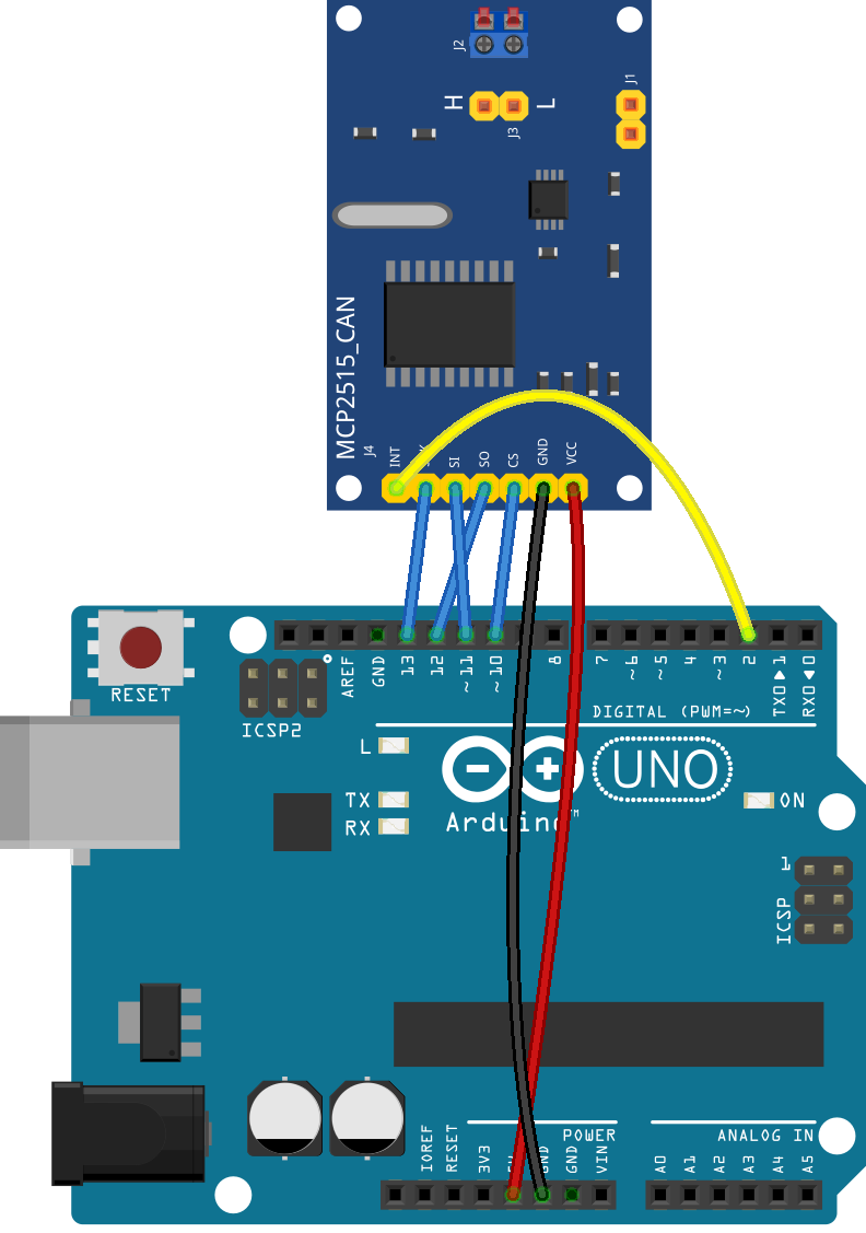
Get the Fritzing code for that diagram HERE.
There are several libraries for the Arduino to interface with the CAN BUS modules. I used the one from here. When you attach your module to the CAN BUS you will need to know its speed and set that value accordingly in the sketch. Also the crystal speed that your module uses (mine is 8Mhz) needs to be specified. Make sure the library you choose (if you don’t use the one I linked to) supports your crystal speed.
For my two module CAN BUS test network, I loaded the send example sketch into one Arduino and the receive example sketch into the other Arduino. I set the crystal speed to 8Mhz (MCP_8MHZ) and the rate to 500Kbps (CAN_500KBPS) in each sketch. The send sketch sends a message every 100ms which the receive sketch then prints to the serial console.
Once you get the modules working, you are ready to attach one of the modules to your cars’ CAN BUS. The only possible change that will need to be made on the Arduino receive sketch is the CAN BUS rate. It needs to match the CAN BUS rate for your specific car. A bit of googling will hopefully get you more information on that.
Hacking your Car with an Arduino and a CAN BUS Module will send a lot of data. The ‘fun’ part is sifting through it to find what electronic components are sending what. Again, on that, GOOGLE is your friend! 🙂
5 comments
Skip to comment form
Hi..
I have speedometer hybrid, already installed in the car.
But any future not showing. can it use module for speedometer? Are u can explain to me step by step program arduino nano – can bus
Thx
Martin
Author
Hi Martin,
You will probably need to do more research into the specific devices you are interested in hooking up. That is always a challenge. Did you try searching to see if anyone else has interfaced your specific hardware to an arduino or other microcontroller system?
Earl
Hi, I’m from Iran and started working with the arduino uno board, I wanted to create a device that would display the car’s ecu items on the small lcd but could not download the code I don’t know which one would win. Please send me where possible. Thankful
Author
Hello! Besides the uno board you will need the can bus module and software to run it. If you use the same module in this post, you can find the software for it here (https://github.com/coryjfowler/MCP_CAN_lib). That has examples (referred to in the post) to get you started. You can display output on the serial console or an LCD.
Hello,
Please, can I read the vehicle odometer with my arduino using this method ?
Can you explain more how to do that ?