Servo Motors

A lot of people when first getting into Arduino projects seem to like robotics. It is fun to create something that you can watch move around. If you are interested in such things, you will be interested to learn about servo motors.


Pictured below is a Parallax Continuous Rotation Servo motor.


Parallax Servo Motor

Parallax Servo Motor

Click the above image or here to learn more about them and download the Arduino sketch to experiment with them.

AVR Raspberry Pi Programmer

There are a number of ways to program AVR microcontroller chips. For my DIY projects, I like to save money by buying components and putting them together to create what I need. I bought some blank ATMEGA 328P micro controllers so that I could make Arduino circuit boards for my projects. Building the Arduino circuit board myself rather than buying the completed Arduino saves money. Granted, it takes more time, but to me it is more satisfying to do it myself.

Since I have blank chips, they need the Arduino Bootloader programmed in. My favorite programmer for that purpose is a Raspberry Pi shown below.

Raspberry Pi Programmer

Raspberry Pi
Programmer

It uses a modified version of AVRDude especially for the Raspberry Pi. Instructions on how to get it and use it are here.

Here is how it is wired.

WIRING THE RPi to the ATMEGA 328

 Code   ATMEGA   RPi  RPi GPIO       Wire
        Pin     Pin    Pin          Color
-------------------------------------------------------
Reset    1      24     GPIO 8 SPI    YELLOW
MOSI    17      19     GPIO 10       BROWN
MISO    18      21     GPIO 9        ORANGE
SCLK    19      23     GPIO 11       BLUE
3.3V    7       17     3.3V          GREEN
GND     8       25     GND           BLACK

The astute observer will note that besides the 6 wires, I have a 16Mgz crystal  on the breadboard. If the chip is blank when it is being programmed this crystal is not needed, however there are times when I reprogram a chip. For those times, the crystal is needed because the fuses are set to use external clocking rather than the internal clock.


The BusPirate (a very useful circuit)

A few days ago my son bought me a birthday present. It was a BusPirate from SparkFun. This is what it looks like plugged into a breadboard.

BusPirate

BusPirate and Breadboard

The BusPirate is quite a handy circuit. I have used it to flash a BIOS chip using FLASHROM  and also program an AVR ATMEGA 328P with AVRDude.

It can even be used in the Arduino IDE as a programmer simply by adding a few lines:

buspirate.name=The Bus Pirate
buspirate.communication=serial
buspirate.protocol=buspirate

in programmers.txt (found in the hardware directory).

The I/O header [breakout] looks like this:

BusPirate I/O Header

BusPirate I/O Header

The BusPirate has many uses, check out the possibilities here.

If you’d like to try some of the functions of the BusPirate on an Arduino, you might be interested in the Arduino Sketch called “MiniPirate“. You can find more information here.

PIR Sensor for your Arduino

A PIR  or Passive Infrared module is really fun to play with. This is what they look like:


Passive Infrared Sensor [front view]Passive Infrared Sensor [back view]


They are basically a motion detector and are called ‘passive’ in the sense that these devices do not generate any energy for detection purposes. They work entirely by detecting the energy given off by other objects in the infrared spectrum wavelengths. More information about infrared can be found here.

Here is how to hook it up:


PIR Fritzing Example

Get the Fritzing source for the above image here. Once you have it hooked up, head on over to the Arduino Playground and get the sketch to make it work.

I added a buzzer and it alerts me when anything (including the cat) sneaks up on me.


Wireless Bluetooth Module for your Arduino

If you’d like to wirelessly attach your Arduino to another device (such as a phone or tablet) via bluetooth, I’d recommend the serial bluetooth module from Elecrow.com.

Here is what they look like:


Serial Bluetooth Module


The module has firmware from BOLUTEK. The PDF document with all of the available BOLUTEK commands is BLK-MD-BC04-B_AT COMMANDS . I also document the AT commands in the sample source code (aduino sketch) below.

There was no sample code that I could find for using these with an Arduino so I wrote my own. The following sketch (load it into any arduino) sets up the module in slave mode so you can connect to it with any blue tooth enabled device. The PIN code is 232323 as you can see from the source.


# Blue Tooth Module Code
# from earl@microcontrollerelectronics.com
#
#include <SoftwareSerial.h>   //Software Serial Port
#define RxD 6
#define TxD 7
#define INTERVAL 10000
long previousMillis = 0;
char recvChar;

SoftwareSerial blueToothSerial(RxD,TxD);

void setup() {
  Serial.begin(9600);
  while (!Serial);
  delay(2000);
  pinMode(RxD, INPUT);
  pinMode(TxD, OUTPUT);
  setupBlueToothConnection();
}

void BT_cmd(String cmd) {
  char recvChar;
  if (cmd != "") {
    blueToothSerial.print(cmd + "\r\n");
    delay(200);
  }
  while(blueToothSerial.available()) {
    recvChar = blueToothSerial.read();
    Serial.print(recvChar);
  }
}

void loop() {
  if(millis() - previousMillis > INTERVAL) {
    previousMillis = millis();
    BT_cmd("AT+STATE");
    BT_cmd("AT+LSP");
  }
  if(blueToothSerial.available()){
    recvChar = blueToothSerial.read();
    Serial.print(recvChar);
  }
  if(Serial.available()){
    recvChar  = Serial.read();
    blueToothSerial.print(recvChar);
  }
}

void setupBlueToothConnection() {
/*
AT                   Check if the command terminal work normally
AT+RESET             Software reboot
AT+VERSION           Get firmware, bluetooth, HCI and LMP version
AT+HELP              List all the commands
AT+NAME              Get/Set local device name
AT+PIN               Get/Set pin code for pairing
AT+BAUD              Get/Set baud rate
AT+CLEAR             Remove the remembered remote address
AT+LADDR             Get local bluetooth address
AT+RNAME             Get remote device name
AT+DEFAULT           Restore factory default
AT+CMODE             Get/Set connection mode
AT+BIND              Get/Set bind bluetooth address
AT+COD               Get/Set local class of device
AT+IAC               Get/Set inquiry access code
AT+ROLE              Get/Set master or slave mode
AT+STATE             Get current state
AT+SENM              Get/Set security and encryption mode
AT+IPSCAN            Get/Set page and inquiry scan parameters
AT+SNIFF             Get/Set sniff power table parameters
AT+LOWPOWER          Start/Stop low power mode
AT+UARTMODE          Get/Set uart stop bits and parity
AT+ENABLEIND         Enable/Disable Indication print
AT+LSP               List Paired Device List
AT+RESETPDL          Reset Paired Device List
AT+REMOVEPDL         Remove one entry from Paired Device List
AT+SUPERVISION       Get/Set supervision timeout
AT+AUTOINQ           Start/Stop auto inquiry
AT+INQ               Start inquiry
AT+INQC              Cancel ongoing inquiry
(M)AT+AUTOCONN       Start/Stop auto connection
(M)AT+INQM           Get/Set inquiry parameters
(M)AT+CONNECT        Connect to a remote device by BD address
*/

  blueToothSerial.begin(9600);
  delay(1000);
  BT_cmd("AT+ENABLEIND1");         //Enable Indications
  BT_cmd("AT+ROLE0");              //set the bluetooth to work in slave mode
  BT_cmd("AT+NAMEArduinoBTSlave"); //set the bluetooth name
  BT_cmd("AT+PIN232323");          //set PIN
  BT_cmd("AT+AUTOINQ1");           //Automatic Search
  Serial.println("\r\nThe slave bluetooth is inquirable!");
}

Connecting an Arduino to a LAN with the ENC28J60

I picked up a couple of these modules:


ENC28J60

from Elecrow.com so I could attach (communicate with and control) several of my Arduinos through a LAN connection.

The main chip is the ENC28J60 from microchip.com. These modules are better than an Ethernet Shield in that you can easily attach these to any Arduino and they are less expensive than a shield.

I have found (and you will too if you GOOGLE this module) that even though they say 3.3V input, they don’t work well at that voltage. They run perfectly when supplied by the Arduino 5V pin.

To run your Arduino sketch pick up a copy of the needed ENC28J60  library from Elecrow here.

Need more information or sample code?  I found the best information about using this module is here:  tweaking4all.com

Careful! Don’t Let the Smoke out!

[warning]Careful! Don’t let the smoke out![/warning]

Hopefully you’ve never ruined any electronics device due to applying too much power. Some people have (cough, cough .. the voice of experience) and when this happens the device or component goes up in smoke. In popular jargon it is said to have “lost its smoke“.

When working with various components, always check their voltage ratings and make sure the input voltage does not exceed those limits.  Also, even with correct voltages, if certain components are wired wrong (like polarized capacitors)  they can still  be damaged.

So it pays to always double check things before you hit that power on button!


OBD-II Testing with an Arduino

OBD-II  (an abbreviation for  On-Board Diagnostics, Second Generation) is a set of standards for implementing a computer based system to control emissions from vehicles ( and a lot more ! ).  If you are not familiar with OBD-II you can read more about it here.

I just recently acquired an OBD-II UART board and cable

OBD-II UARTOBD-II Cable

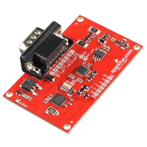
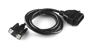
from SparkFun.com, so I can diagnose any car problems. One end of the cable connects to the OBD-II connector on your car, the other end connects to the board.  The board can then connect to any serial port via a 6 pin header that needs to be soldered on.

The 6 pin header connects nicely to an FTDI board

FTDI Breakout 5V

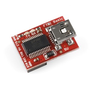
that Sparkfun.com also sells.  The tutorial about this product shows how to attach an arduino and LCD monitor to capture data from your cars’ computer.

The board did not come with any OBD-II diagnostic / analysis software but there are a number of FREE and commercial offerings to choose from.

I like to write my own software and so I came up with this Python script to inquire for and analyze the OBD information. It is too big to post here so just click on the image to download it.

Python_small

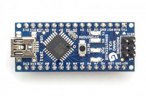
If you’d like to test the Python code but do not have the OBD-II UART, you can substitute any Arduino you might have lying around. I wrote a simple sketch to emulate the OBD-II information coming from a ‘sample’ car. Just attach the arduino to your computer via any USB cable, load the sketch and run the Python script.

I tested it with my Aduino Nano.
Arduino Nano

Here is the sketch:

# Arduino Sketch to emulate an OBD-II connection
# from earl@microcontrollerelectronics.com
#
String inputString     = "";
boolean stringComplete = false;

void setup() {
  Serial.begin(9600);
  inputString.reserve(200);
  Serial.println(">");
}

void loop() {
  if (stringComplete) {
    int    len = inputString.length();
    String ans = "4" + inputString.substring(1,2) + " ";

    if (len > 4)      ans = ans + inputString.substring(3,5) + ":";
    else if (len > 3) ans = ans + inputString.substring(2,4) + ":";
    else if (len > 2) ans = ans + inputString.substring(3,4) + ":";

    if      (inputString.substring(0,3) == "ATZ")   Serial.println("ELM327 v1.4");
    else if (inputString.substring(0,2) == "AT")    Serial.println("OK");
    else if (inputString.substring(0,5) == "01 00") Serial.println("41 00:FF FF FC FF");
    else if (inputString.substring(0,5) == "01 01") Serial.println("41 01:84 07 61 00");
    else if (inputString.substring(0,5) == "01 20") Serial.println("41 20:FF FF FC FF");
    else if (inputString.substring(0,5) == "01 40") Serial.println("41 40:FF FF FC FF");
    else if (inputString.substring(0,5) == "01 60") Serial.println("41 60:FF FF FC FF");
    else if (inputString.substring(0,5) == "01 80") Serial.println("41 80:FF FF FC FF");
    else if (inputString.substring(0,5) == "01 A0") Serial.println("41 A0:FF FF FC FF");
    else if (inputString.substring(0,5) == "01 C0") Serial.println("41 C0:FF FF FC FF");
    else if (inputString.substring(0,2) == "01")    Serial.println(ans + "00 00 00 00");
    else if (inputString.substring(0,2) == "03")    Serial.println("43 03 00 03 01 03\r\n43 13 01 04");
    else if (inputString.substring(0,5) == "09 02") Serial.println("49 02:1Z3768470804");
    else                                            Serial.println(ans + "NO DATA");
    Serial.println(">");
    inputString = "";
    stringComplete = false;
  }
}

void serialEvent() {
  while (Serial.available()) {
    char inChar = (char)Serial.read();
    if (inChar == '\n') continue;
    if (inChar == '\r') {
      stringComplete = true;
      if (inputString == "") inputString = "NULL";
      inputString.toUpperCase();
      continue;
    }
    inputString += inChar;
  }
}

Atmel versus PIC Microcontrollers

Many years ago (I am old  ;-)) I was asked which microcontrollers are  best, ones from PIC (microchip.com) or ones from  Atmel (atmel.com).

At the time I was asked, there was a lot of discussion about chip architecture, instruction sets and which chip was best.

I thought at the time and still feel this way, it depends on too many factors to say which is best.

Certainly with the popularity of the Arduino the Atmega series of chips from Atmel got a boost in popularity.

For most of my projects, I find myself using an Atmega 328p mostly because I can buy it locally in my favorite electronics store cheaply and It is easily programmed with the Arduino IDE.


Fritzing Circuit Design Software

If you need a way to design a circuit or show a nice graphic of it for someone else to follow, you might consider Fritzing from fritzing.org.

A quote from their website:

Fritzing is an open-source hardware initiative that makes electronics accessible as a creative material for anyone. Fritzing.org offers a software tool, a community website and services in the spirit of Processing and Arduino, fostering a creative ecosystem that allows users to document their prototypes, share them with others, teach electronics in a classroom,and layout and manufacture professional pcbs.


Fritzing software is vector based so you can, drag and drop circuit components, easily re-size and attach wires.

It allows you to make COOL looking graphics like this:

fritzing

The Fritzing software comes with an extensive libary of components, however there are others who have created libraries of parts too. One of my favorite  Internet  hangouts is Adafruit.com. They have created a Fritzing library of parts which you can find on Github here.

Load more