With just a few sensors, one can determine a lot about the weather.
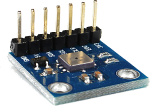
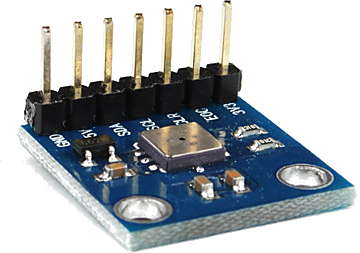
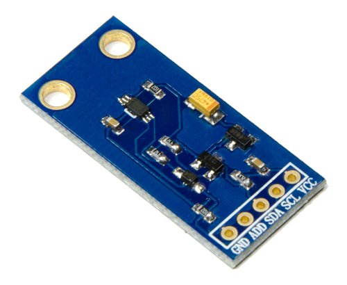
BMP085
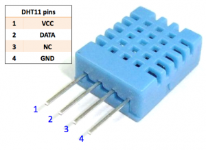
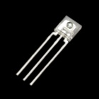
DHT11
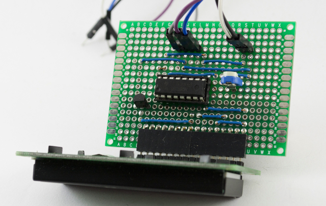
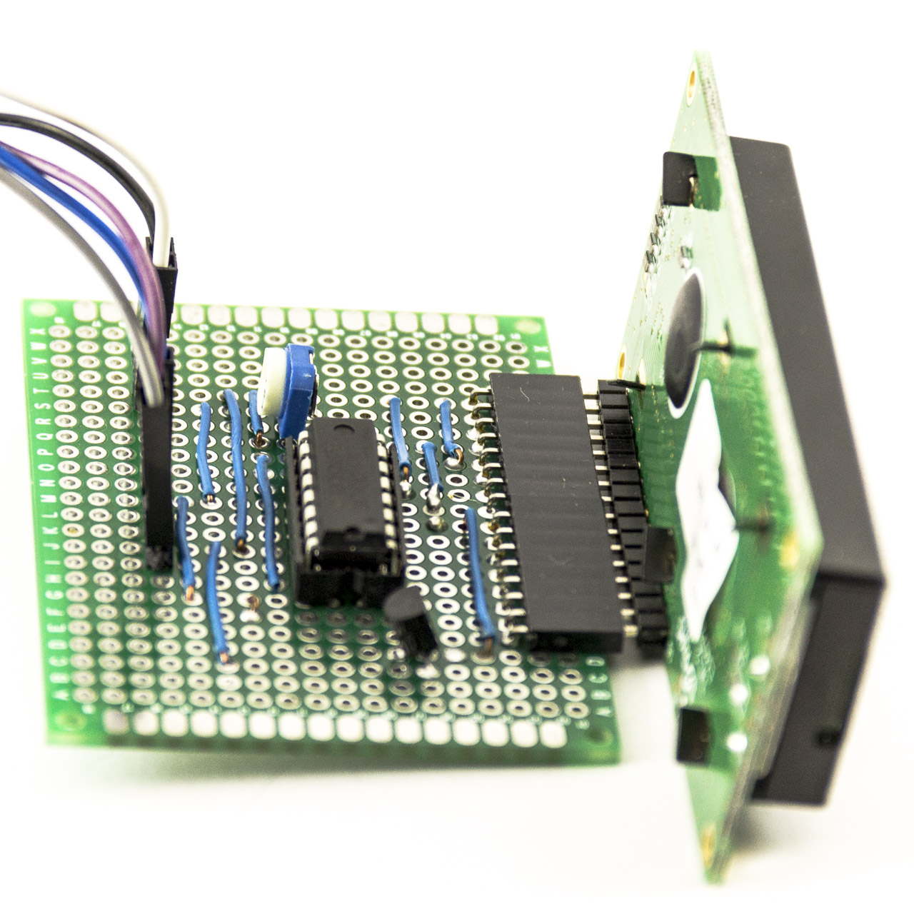
The BMP085 can be used to sense barometric pressure and temperature and the DHT11 can be used to sense humidity and also temperature.
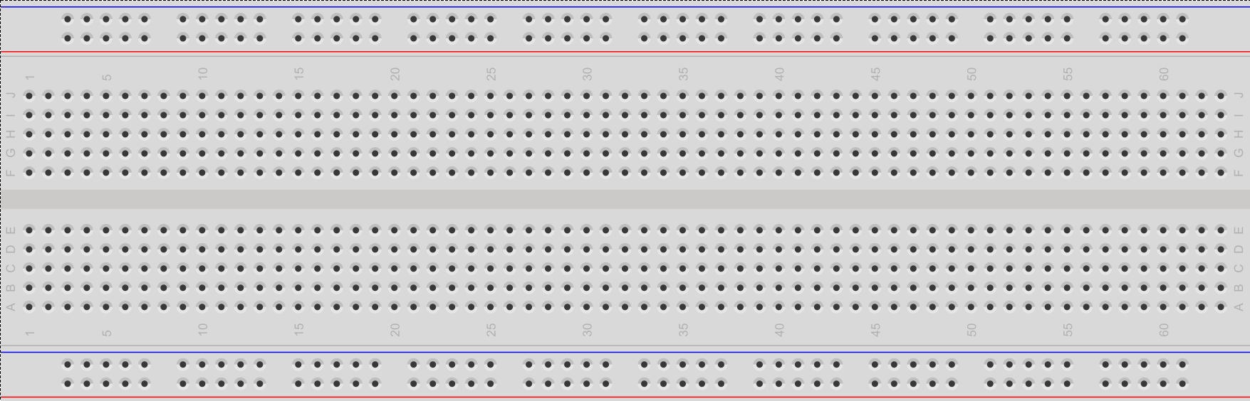
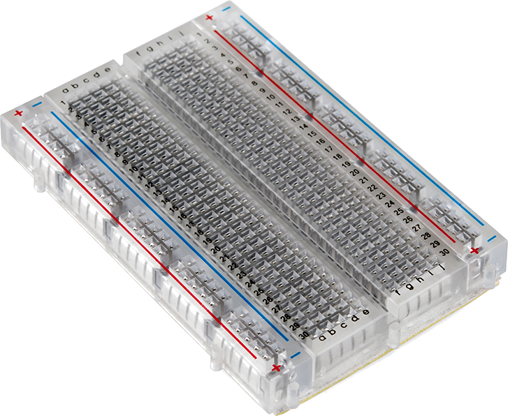
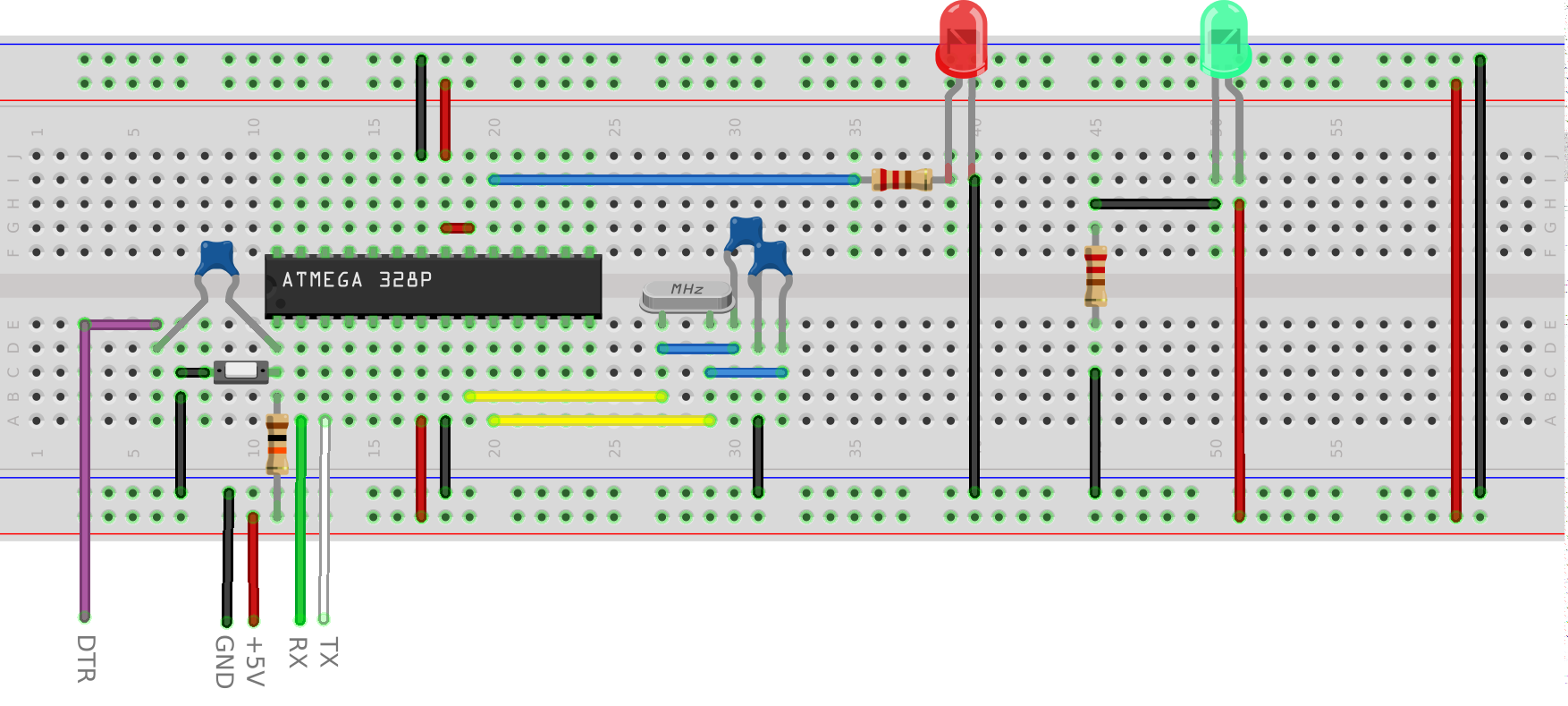
Here is what they look like attached to a mini breadboard:
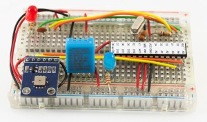
Arudino Breadboard Weather Station
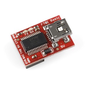
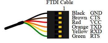
An FTDI cable (not shown in the above image) can be plugged in at the top left of the breadboard to power this circuit and collect the data.
To collect data in an arduino sketch. the DHT library and the Wire Library will be needed. Both of which are included in the Aruduino IDE.
Here is the arduino sketch (code) to display barometric pressure, humidity and temperature (from both devices) :
// Weather Station DHT11 & BMP085
// from earl@microcontrollerelectronics.com

#include "DHT.h"
#include <Wire.h>

#define DHTPIN 8
#define LED    9
#define DHTTYPE DHT11
#define BMP085_ADDRESS 0x77

const unsigned char OSS = 0;
int ac1;
int ac2;
int ac3;
unsigned int ac4;
unsigned int ac5;
unsigned int ac6;
int b1;
int b2;
int mb;
int mc;
int md;
long b5;

DHT dht(DHTPIN, DHTTYPE);

void setup() {
  Serial.begin(9600);
  dht.begin();
  pinMode(LED, OUTPUT);
  Wire.begin();
  bmp085Calibration();
}

void loop() {

  float h = dht.readHumidity();
  float t = dht.readTemperature();
  float f = t * 1.8 + 32.0;

  digitalWrite(LED, HIGH);

  Serial.println("--start-\n");

  Serial.println("Sensor: DHT11");
  if (isnan(t) || isnan(h)) {
    Serial.println("Failed to read from DHT");
  } else {
    Serial.print("Humidity: ");
    Serial.print(h);
    Serial.println(" %");
    Serial.print("Temperature: ");
    Serial.print(t);
    Serial.println(" °C");
    Serial.print("Temperature: ");
    Serial.print(f);
    Serial.println(" °F");
    Serial.println("");
  }

  float temperature   = bmp085GetTemperature(bmp085ReadUT()); //MUST be called first
  float pressure      = bmp085GetPressure(bmp085ReadUP());
  float atm           = pressure / 101325; // "standard atmosphere"
//  float altitude      = calcAltitude(pressure); //Uncompensated caculation - in Meters
  float temperature_F = (temperature * 1.8) + 32;

  Serial.println("Sensor: BMP085");
  Serial.print("Temperature: ");
  Serial.print(temperature, 2); //display 2 decimal places
  Serial.println(" °C");

  Serial.print("Temperature: ");
  Serial.print(temperature_F, 2); //display 2 decimal places
  Serial.println(" °F");

  Serial.print("Pressure: ");
  Serial.print(pressure, 0); //whole number only.
  Serial.println(" Pascals");

  Serial.print("Standard Atmosphere: ");
  Serial.println(atm, 4); //display 4 decimal places

//  Serial.print("Altitude: ");
//  Serial.print(altitude, 2); //display 2 decimal places
//  Serial.println(" M");

  Serial.println("");
  Serial.println("--end-\n");

  delay(250);
  digitalWrite(LED, LOW);

  delay(5000);
}


// Stores all of the bmp085's calibration values into global variables
// Calibration values are required to calculate temp and pressure
// This function should be called at the beginning of the program
void bmp085Calibration()
{
  ac1 = bmp085ReadInt(0xAA);
  ac2 = bmp085ReadInt(0xAC);
  ac3 = bmp085ReadInt(0xAE);
  ac4 = bmp085ReadInt(0xB0);
  ac5 = bmp085ReadInt(0xB2);
  ac6 = bmp085ReadInt(0xB4);
  b1 = bmp085ReadInt(0xB6);
  b2 = bmp085ReadInt(0xB8);
  mb = bmp085ReadInt(0xBA);
  mc = bmp085ReadInt(0xBC);
  md = bmp085ReadInt(0xBE);
}

// Calculate temperature in deg C
  float bmp085GetTemperature(unsigned int ut){
  long x1, x2;

  x1 = (((long)ut - (long)ac6)*(long)ac5) >> 15;
  x2 = ((long)mc << 11)/(x1 + md);
  b5 = x1 + x2;

  float temp = ((b5 + 8)>>4);
  temp = temp /10;

  return temp;
}

// Calculate pressure given up
// calibration values must be known
// b5 is also required so bmp085GetTemperature(...) must be called first.
// Value returned will be pressure in units of Pa.
  long bmp085GetPressure(unsigned long up){
  long x1, x2, x3, b3, b6, p;
  unsigned long b4, b7;

  b6 = b5 - 4000;
  // Calculate B3
  x1 = (b2 * (b6 * b6)>>12)>>11;
  x2 = (ac2 * b6)>>11;
  x3 = x1 + x2;
  b3 = (((((long)ac1)*4 + x3)<<OSS) + 2)>>2;

  // Calculate B4
  x1 = (ac3 * b6)>>13;
  x2 = (b1 * ((b6 * b6)>>12))>>16;
  x3 = ((x1 + x2) + 2)>>2;
  b4 = (ac4 * (unsigned long)(x3 + 32768))>>15;

  b7 = ((unsigned long)(up - b3) * (50000>>OSS));
  if (b7 < 0x80000000)
    p = (b7<<1)/b4;
  else
    p = (b7/b4)<<1;

  x1 = (p>>8) * (p>>8);
  x1 = (x1 * 3038)>>16;
  x2 = (-7357 * p)>>16;
  p += (x1 + x2 + 3791)>>4;

  long temp = p;
  return temp;
}

// Read 1 byte from the BMP085 at 'address'
char bmp085Read(unsigned char address)
{
  unsigned char data;

  Wire.beginTransmission(BMP085_ADDRESS);
  Wire.write(address);
  Wire.endTransmission();

  Wire.requestFrom(BMP085_ADDRESS, 1);
  while(!Wire.available());

  return Wire.read();
}

// Read 2 bytes from the BMP085
// First byte will be from 'address'
// Second byte will be from 'address'+1
int bmp085ReadInt(unsigned char address)
{
  unsigned char msb, lsb;

  Wire.beginTransmission(BMP085_ADDRESS);
  Wire.write(address);
  Wire.endTransmission();

  Wire.requestFrom(BMP085_ADDRESS, 2);
  while(Wire.available()<2);
  msb = Wire.read();
  lsb = Wire.read();

  return (int) msb<<8 | lsb;
}

// Read the uncompensated temperature value
unsigned int bmp085ReadUT(){
  unsigned int ut;

  // Write 0x2E into Register 0xF4
  // This requests a temperature reading
  Wire.beginTransmission(BMP085_ADDRESS);
  Wire.write(0xF4);
  Wire.write(0x2E);
  Wire.endTransmission();

  // Wait at least 4.5ms
  delay(5);

  // Read two bytes from registers 0xF6 and 0xF7
  ut = bmp085ReadInt(0xF6);
  return ut;
}

// Read the uncompensated pressure value
unsigned long bmp085ReadUP(){

  unsigned char msb, lsb, xlsb;
  unsigned long up = 0;

  // Write 0x34+(OSS<<6) into register 0xF4
  // Request a pressure reading w/ oversampling setting
  Wire.beginTransmission(BMP085_ADDRESS);
  Wire.write(0xF4);
  Wire.write(0x34 + (OSS<<6));
  Wire.endTransmission();

  // Wait for conversion, delay time dependent on OSS
  delay(2 + (3<<OSS));

  // Read register 0xF6 (MSB), 0xF7 (LSB), and 0xF8 (XLSB)
  msb = bmp085Read(0xF6);
  lsb = bmp085Read(0xF7);
  xlsb = bmp085Read(0xF8);

  up = (((unsigned long) msb << 16) | ((unsigned long) lsb << 8) | (unsigned long) xlsb) >> (8-OSS);

  return up;
}


void writeRegister(int deviceAddress, byte address, byte val) {
  Wire.beginTransmission(deviceAddress); // start transmission to device
  Wire.write(address);       // send register address
  Wire.write(val);         // send value to write
  Wire.endTransmission();     // end transmission
}

int readRegister(int deviceAddress, byte address){

  int v;
  Wire.beginTransmission(deviceAddress);
  Wire.write(address); // register to read
  Wire.endTransmission();

  Wire.requestFrom(deviceAddress, 1); // read a byte

  while(!Wire.available()) ; // waiting

  v = Wire.read();
  return v;
}

float calcAltitude(float pressure){

  float A = pressure/101325;
  float B = 1/5.25588;
  float C = pow(A,B);
  C = 1 - C;
  C = C /0.0000225577;

  return C;
}
Update 11/5/2020, things have changed in the Arduino IDE and libraries since this was first posted. Here is an updated sketch:
// Weather Station DHT11 & BMP085
// from earl@microcontrollerelectronics.com

#include <DHT11.h>
#include <Wire.h>

#define DHT11PIN 8
#define LED      9
#define BMP085_ADDRESS 0x77

DHT11 dht11(DHT11PIN);
const unsigned char OSS = 0;
int ac1;
int ac2;
int ac3;
unsigned int ac4;
unsigned int ac5;
unsigned int ac6;
int b1;
int b2;
int mb;
int mc;
int md;
long b5;
float t, h, f;
int err;

void setup() {
  Serial.begin(9600);
  pinMode(LED, OUTPUT);
  Wire.begin();
  bmp085Calibration();
}

void loop() {

if ((err=dht11.read(h, t))==0){
  float f = t * 1.8 + 32.0;

  digitalWrite(LED, HIGH);

  Serial.println("--start-\n");

  Serial.println("Sensor: DHT11");
  if (isnan(t) || isnan(h)) {
    Serial.println("Failed to read from DHT");
  } else {
    Serial.print("Humidity: ");
    Serial.print(h);
    Serial.println(" %");
    Serial.print("Temperature: ");
    Serial.print(t);
    Serial.println(" °C");
    Serial.print("Temperature: ");
    Serial.print(f);
    Serial.println(" °F");
    Serial.println("");
  }

  float temperature   = bmp085GetTemperature(bmp085ReadUT()); //MUST be called first
  float pressure      = bmp085GetPressure(bmp085ReadUP());
  float atm           = pressure / 101325; // "standard atmosphere"
//  float altitude      = calcAltitude(pressure); //Uncompensated caculation - in Meters
  float temperature_F = (temperature * 1.8) + 32;

  Serial.println("Sensor: BMP085");
  Serial.print("Temperature: ");
  Serial.print(temperature, 2); //display 2 decimal places
  Serial.println(" °C");

  Serial.print("Temperature: ");
  Serial.print(temperature_F, 2); //display 2 decimal places
  Serial.println(" °F");

  Serial.print("Pressure: ");
  Serial.print(pressure, 0); //whole number only.
  Serial.println(" Pascals");

  Serial.print("Standard Atmosphere: ");
  Serial.println(atm, 4); //display 4 decimal places

//  Serial.print("Altitude: ");
//  Serial.print(altitude, 2); //display 2 decimal places
//  Serial.println(" M");

  Serial.println("");
  Serial.println("--end-\n");

  delay(250);
  digitalWrite(LED, LOW);


}
  delay(5000);
}

// Stores all of the bmp085's calibration values into global variables
// Calibration values are required to calculate temp and pressure
// This function should be called at the beginning of the program
void bmp085Calibration()
{
  ac1 = bmp085ReadInt(0xAA);
  ac2 = bmp085ReadInt(0xAC);
  ac3 = bmp085ReadInt(0xAE);
  ac4 = bmp085ReadInt(0xB0);
  ac5 = bmp085ReadInt(0xB2);
  ac6 = bmp085ReadInt(0xB4);
  b1 = bmp085ReadInt(0xB6);
  b2 = bmp085ReadInt(0xB8);
  mb = bmp085ReadInt(0xBA);
  mc = bmp085ReadInt(0xBC);
  md = bmp085ReadInt(0xBE);
}

// Calculate temperature in deg C
  float bmp085GetTemperature(unsigned int ut){
  long x1, x2;

  x1 = (((long)ut - (long)ac6)*(long)ac5) >> 15;
  x2 = ((long)mc << 11)/(x1 + md);
  b5 = x1 + x2;

  float temp = ((b5 + 8)>>4);
  temp = temp /10;

  return temp;
}

// Calculate pressure given up
// calibration values must be known
// b5 is also required so bmp085GetTemperature(...) must be called first.
// Value returned will be pressure in units of Pa.
  long bmp085GetPressure(unsigned long up){
  long x1, x2, x3, b3, b6, p;
  unsigned long b4, b7;

  b6 = b5 - 4000;
  // Calculate B3
  x1 = (b2 * (b6 * b6)>>12)>>11;
  x2 = (ac2 * b6)>>11;
  x3 = x1 + x2;
  b3 = (((((long)ac1)*4 + x3)<<OSS) + 2)>>2;

  // Calculate B4
  x1 = (ac3 * b6)>>13;
  x2 = (b1 * ((b6 * b6)>>12))>>16;
  x3 = ((x1 + x2) + 2)>>2;
  b4 = (ac4 * (unsigned long)(x3 + 32768))>>15;

  b7 = ((unsigned long)(up - b3) * (50000>>OSS));
  if (b7 < 0x80000000)
    p = (b7<<1)/b4;
  else
    p = (b7/b4)<<1;

  x1 = (p>>8) * (p>>8);
  x1 = (x1 * 3038)>>16;
  x2 = (-7357 * p)>>16;
  p += (x1 + x2 + 3791)>>4;

  long temp = p;
  return temp;
}

// Read 1 byte from the BMP085 at 'address'
char bmp085Read(unsigned char address)
{
  unsigned char data;

  Wire.beginTransmission(BMP085_ADDRESS);
  Wire.write(address);
  Wire.endTransmission();

  Wire.requestFrom(BMP085_ADDRESS, 1);
  while(!Wire.available());

  return Wire.read();
}

// Read 2 bytes from the BMP085
// First byte will be from 'address'
// Second byte will be from 'address'+1
int bmp085ReadInt(unsigned char address)
{
  unsigned char msb, lsb;

  Wire.beginTransmission(BMP085_ADDRESS);
  Wire.write(address);
  Wire.endTransmission();

  Wire.requestFrom(BMP085_ADDRESS, 2);
  while(Wire.available()<2);
  msb = Wire.read();
  lsb = Wire.read();

  return (int) msb<<8 | lsb;
}

// Read the uncompensated temperature value
unsigned int bmp085ReadUT(){
  unsigned int ut;

  // Write 0x2E into Register 0xF4
  // This requests a temperature reading
  Wire.beginTransmission(BMP085_ADDRESS);
  Wire.write(0xF4);
  Wire.write(0x2E);
  Wire.endTransmission();

  // Wait at least 4.5ms
  delay(5);

  // Read two bytes from registers 0xF6 and 0xF7
  ut = bmp085ReadInt(0xF6);
  return ut;
}

// Read the uncompensated pressure value
unsigned long bmp085ReadUP(){

  unsigned char msb, lsb, xlsb;
  unsigned long up = 0;

  // Write 0x34+(OSS<<6) into register 0xF4
  // Request a pressure reading w/ oversampling setting
  Wire.beginTransmission(BMP085_ADDRESS);
  Wire.write(0xF4);
  Wire.write(0x34 + (OSS<<6));
  Wire.endTransmission();

  // Wait for conversion, delay time dependent on OSS
  delay(2 + (3<<OSS));

  // Read register 0xF6 (MSB), 0xF7 (LSB), and 0xF8 (XLSB)
  msb = bmp085Read(0xF6);
  lsb = bmp085Read(0xF7);
  xlsb = bmp085Read(0xF8);

  up = (((unsigned long) msb << 16) | ((unsigned long) lsb << 8) | (unsigned long) xlsb) >> (8-OSS);

  return up;
}


void writeRegister(int deviceAddress, byte address, byte val) {
  Wire.beginTransmission(deviceAddress); // start transmission to device
  Wire.write(address);       // send register address
  Wire.write(val);         // send value to write
  Wire.endTransmission();     // end transmission
}

int readRegister(int deviceAddress, byte address){

  int v;
  Wire.beginTransmission(deviceAddress);
  Wire.write(address); // register to read
  Wire.endTransmission();

  Wire.requestFrom(deviceAddress, 1); // read a byte

  while(!Wire.available()) ; // waiting

  v = Wire.read();
  return v;
}

float calcAltitude(float pressure){

  float A = pressure/101325;
  float B = 1/5.25588;
  float C = pow(A,B);
  C = 1 - C;
  C = C /0.0000225577;

  return C;
}

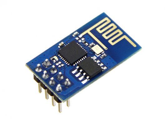
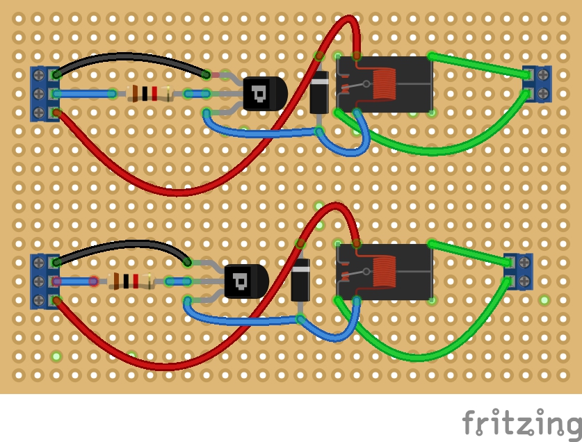
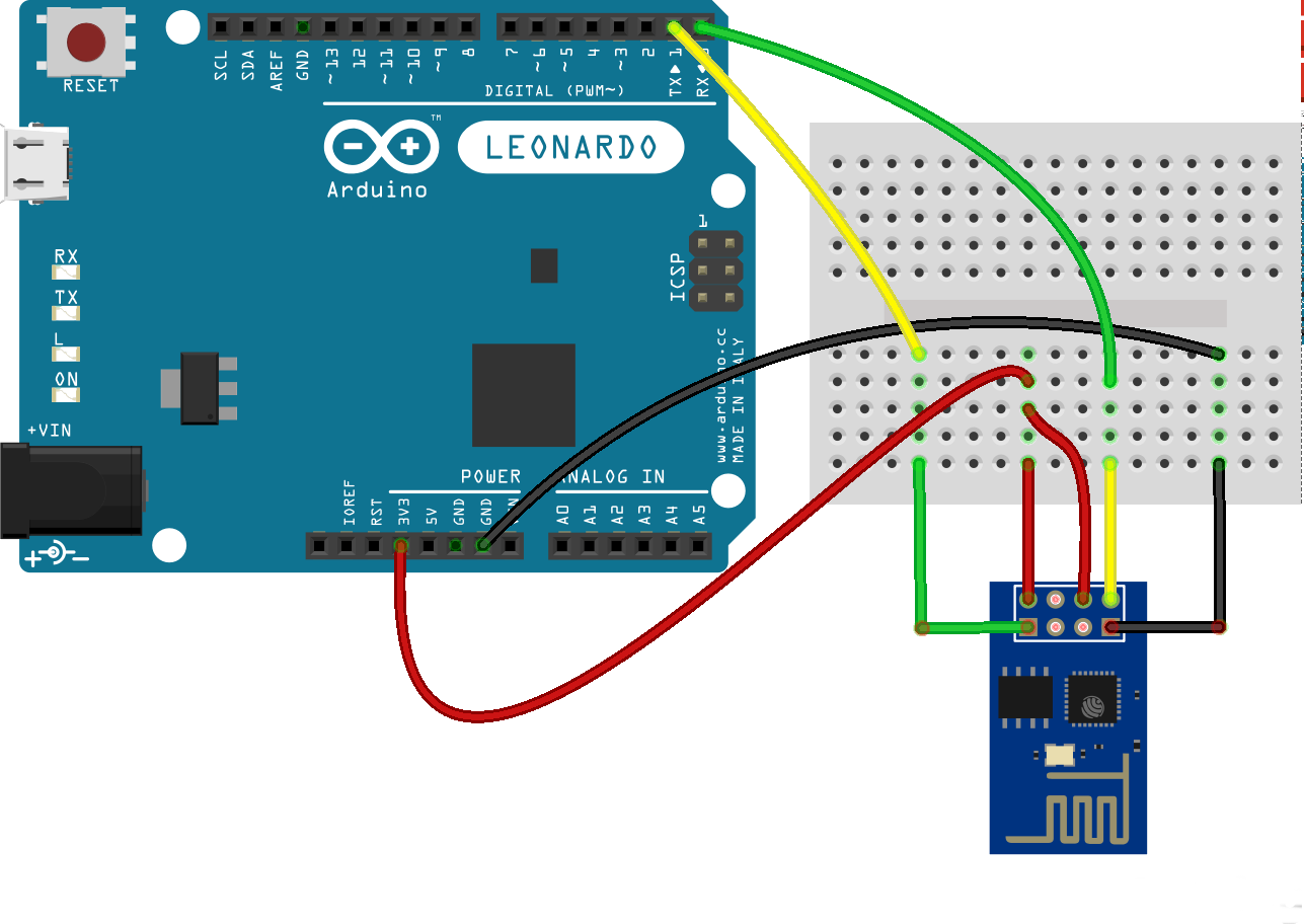 you can get the Fritzing file here. (The Fritzing part for the ESP8266 can be found here.) Notice that the TX and RX serial connections ‘crossover’. Not crossing over is a common mistake when first hooking up a serial communications device.
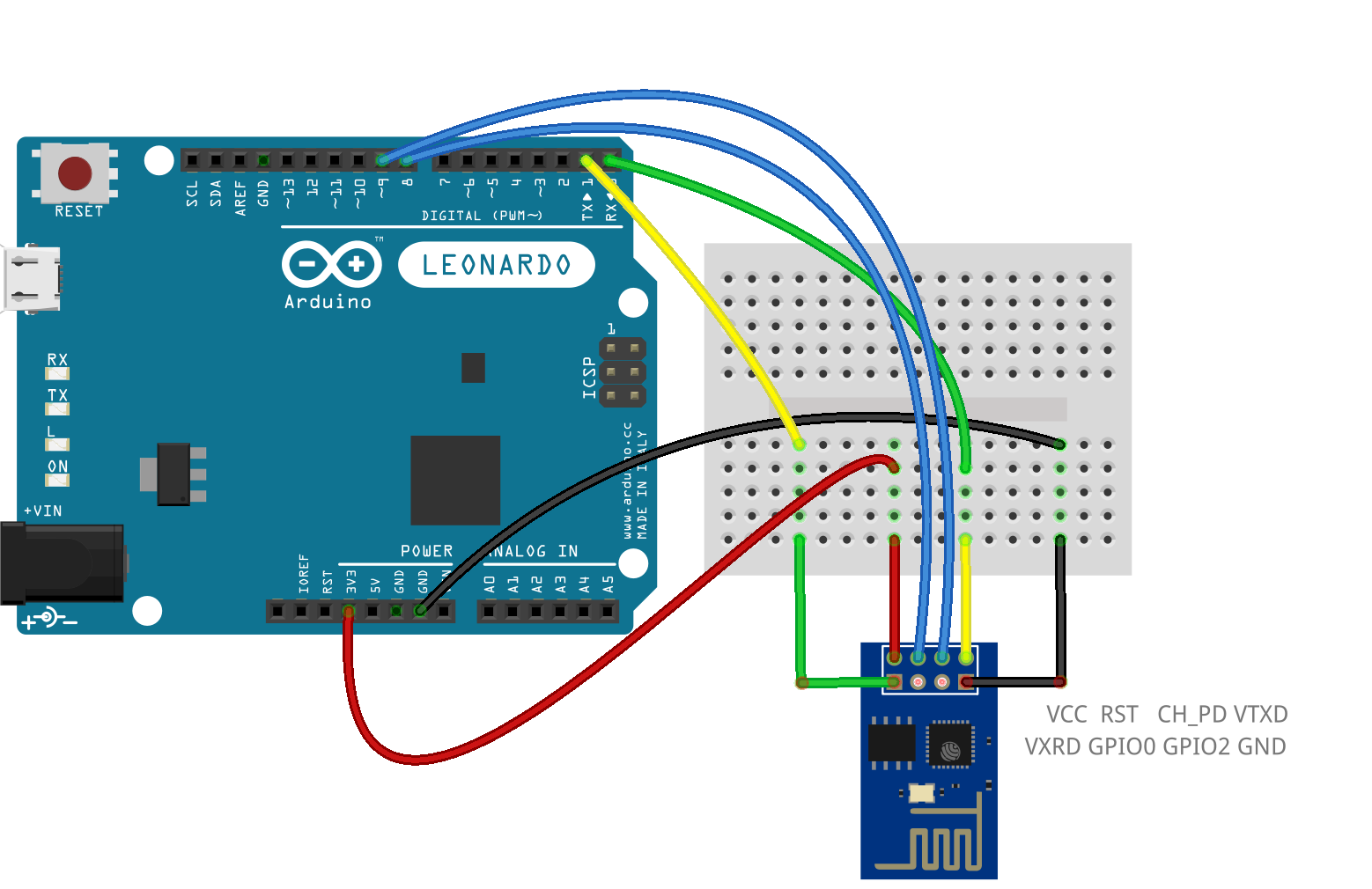


Recent Comments