LM317 to output 3.3 Volts

I created a simple circuit using the LM317 to output 3.3 volts from a 5V or greater input voltage. Why? Because, a number of modules for the Arduino (or Pinguino) take 3.3 Volts. It’s true, some of the Arduinos do have a 3.3V voltage regulator (and thus a source of 3.3V), however, that might not have sufficient amperage. Also, if  you are a fan of the DIY (Do-It-Yourself)  Pinguinos (as I am), you will need a 3.3V source to accompany them since they do not have one.

So, it is quite handy to have a 3.3V power source around! Here is what the circuit looks like:

LM317 3.3 V Circuit Top ViewLM317 Circuit Side View

I save the foam pads, that came with PC motherboards I bought, and cut out pieces to place under the circuits I make to protect against short circuits. The pads are held in place with two-sided sticky tape.

Here Is the Fritzing circuit diagram:


LM317 3.3V Circuit Diagram

If you’d like the Fritzing source to the above diagram, download it from here.

The LM317 is an adjustable  linear voltage regulator. It can take an input voltage of 3-40 Volts DC and outputs a fixed voltage from 1.2 to 37 Volts DC. The output is controlled by resistors on the adjustment pin. Here is a handy calculator to calculate the resistance needed to obtain the desired output voltage. I use 545 Ohms (470 + 75) to output the desired 3.3V.

Notice that I have a two pin header or a power jack as input source (on the right of the pictures) and the output is a two pin header (on the left in the pictures).

I tested this circuit using the ESP8266 and the NL6621-Y1 modules that I wrote about in earlier articles. These modules require 3.3V and both worked fine.

I thought about integrating this circuit on the DIY Pinguino boards I made and might do that next time I get around to making more of them. However, I think the stand alone circuit is more flexible to use. For example, you can attach a USB to RS-232 cable (like this):

USB to Serial Cabledirectly to the circuit (5V Input and GND) and to the wireless module (Tx and Rcv from the cable, 3.3V and GND from the circuit)  and not even need an Arduino / Pinguino.

Serial Port Communication via Python

There are many Linux (and Windows) programs ‘out there’ that allow you to do serial port communications.  However, I needed some things that those programs did not provide (on my Linux system) so I came up with my Serial Port Communication via Python script. If you want something that you can learn from and/or customize further this script is for you (if you are using Linux that is). Here is the script:

                                Serial Port Communication via Python

It takes from zero to two parameters. Given no parameters, it defaults to 115200 BAUD and will search for ‘active’ serial ports with the name /dev/ttyUSB* or /dev/ttyACM* and use the first one it finds. If you want to override or specify either the serial port or BAUD rate just give it either or both parameters. If you give it both parameters, they can be in any order as the script can tell what is a port versus what is the rate. When running, the script will ‘echo’ any characters coming from the serial port to the console and ‘echo’ any characters typed in from the console to the serial port. Use a Ctrl-C to exit the script. Note that the comments tell you how to change certain features of the program.

With this script you have basic serial port communications (quite usable) and it can be easily added to for enhanced functionality.

Again, there are other serial communication programs/scripts (which run under Linux). Perhaps the most common one used is minicom. Another quite useful program is screen.  Although screen is primarily used as a terminal multiplexer (i.e. using virtual terminals in a login session), it can be used as a serial terminal communication program too. For example:

screen /dev/ttyUSB0 115200

Also note that the Arduino IDE has a built in serial monitor (the newer versions have a serial plotter too) so that serial communications with your Arduino is relatively easy during code development. The Pinguino IDE does not have a serial monitor built in so my script can be used for that sometimes needed functionality.

You may notice that this script is an updated version of one I wrote about before (here) which I used to communicate with the Arduino MiniPirate sketch.

If you do put my script to use or enhance it, i’d be interested to see what features you add. Leave a comment!

FS1000A Wireless RF433 Transmit and Receive Module Pair

I like experimenting with wireless devices, as you can tell from the many posts about them here! 😎 I am trying out an FS1000A Wireless RF433 Transmit and Receive Module pair this time.

They use use the RF 433Mhz  frequency with ASK modulation. (You can also get these with the 315Mz frequency instead.)  I got mine from Elecrow.com.  They look like this:

FS1000A Wireless RF433 Transmit and Receive Module Pair


FS1000A RF433 Transmit and Receive Module PairHere is a graphic on how they work together:

FS1000A Wireless RF433 Transmit and Receive Module PairBasically you can use one Arduino to control the Transmitter and one Arduino to control the Receiver. An Arduino RF library comes in handy for that. In the past, you’d use the VirtualWire library for controlling these modules, now however, there is a better library called RadioHead which supersedes it. Download it from HERE. Once you install it from the Arduino IDE (Sketch -> Include Library -> Add .ZIP Library) there will be a number of examples to choose from. You can use the File -> Examples -> RadioHead -> Ask -> ask_receiver and ask_transmitter sketches.

I modified them a bit as shown below.

Here is the sketch for the Arduino Receiver:

Here is the sketch for the Arduino Transmitter:

As you can tell from the comments in the code, they are very easy to hook up. Both use only three pins (VCC, GND and DATA). Here is the Fritzing Diagram showing how they are connected:

FS1000A RF433 Transmit and Receive ModulesYou can download the custom fritzing parts from here. If you want my fritzing diagram, download it from here.

Updated Note (6/21/2018): In the receiver code, the printBuffer function ‘dumps’ the buffer in HEX (probably for better diagnostics). Here is the code for the receiver, if you want a normal print of the received characters:

NL6621-Y1 Wireless Module

There is a new kid on the block, the NL6621-Y1 Wireless Module from Nufront.  The NL6621 WiFi SOC is powered by a 160 MHz ARM Cortex-M3 (NL6621M). Everything is integrated in the NL6621M SOC including 448KB of RAM.

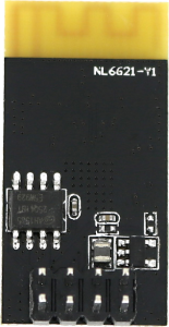
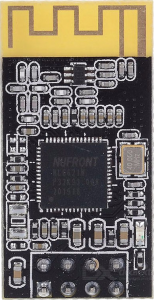
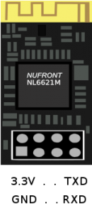
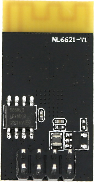
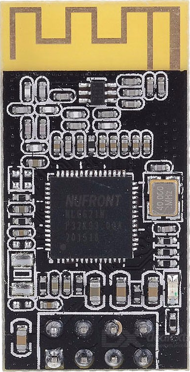
Here is what the NL6621-Y1 wireless module looks like:


The NL6621-Y1 wireless module Back Image The NL6621 wireless module Front Image The NL6621 wireless module PCB Layout


Supposedly it is much better than the ESP8266 from Expressif. However, the ESP8266 has a lot of code and documentation for it whereas there is very little information or code for the  NL6621-Y1 wireless module (as of this post).

Nufront does have several GitHub repositories for it here:

https://github.com/NufrontIOT

The common module (NL6621-Y1) seems to have the NL6621_SerialNet_SDK installed as that is what services the serial AT command set which allows the module to be configured via a serial interface.

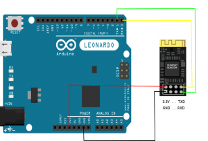
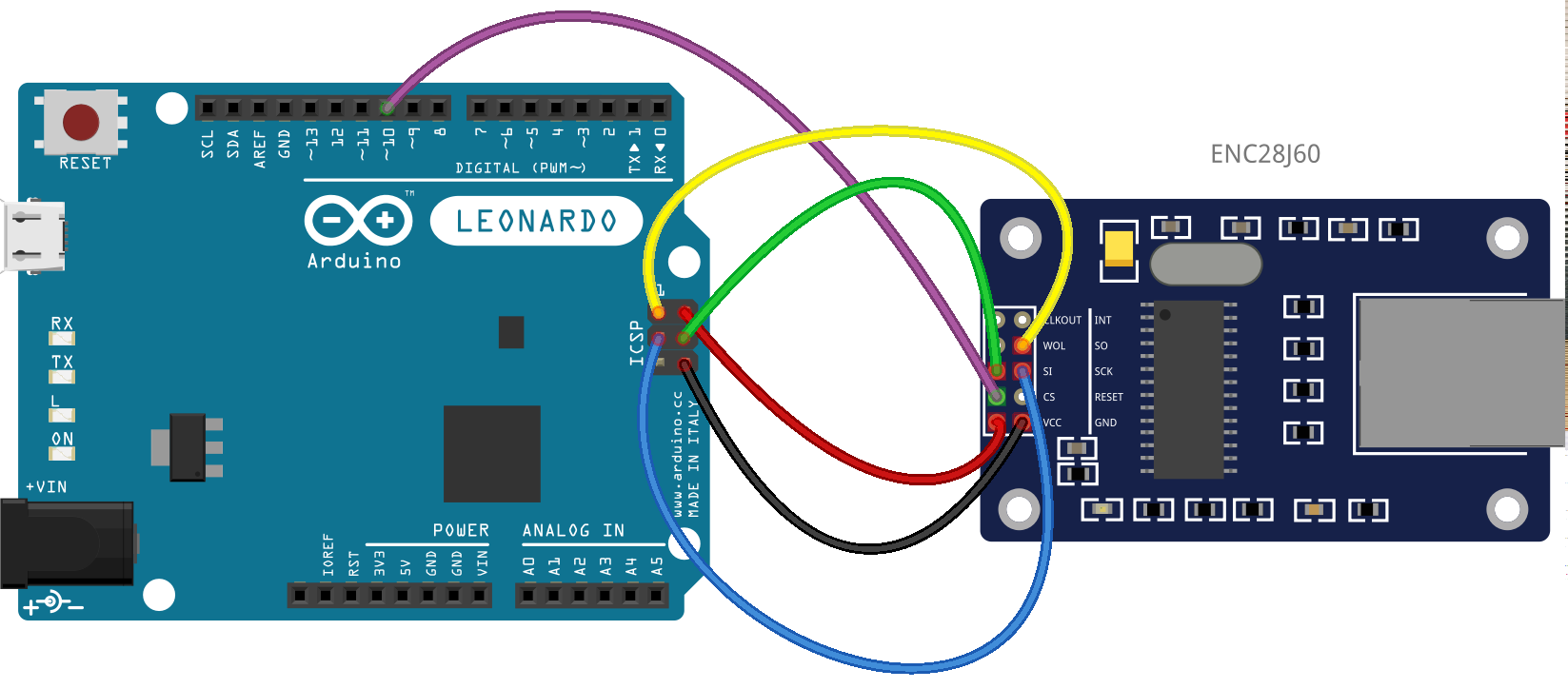
I have the NL6621-Y1 wireless module from Elecrow and I wanted to see if I could get it working (attached to an Arduino Leonardo) similar to how I attached an ESP8266 in an earlier post.

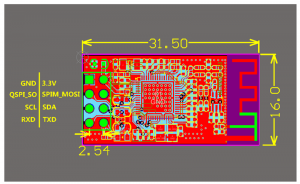
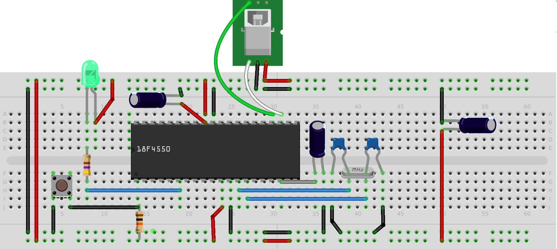
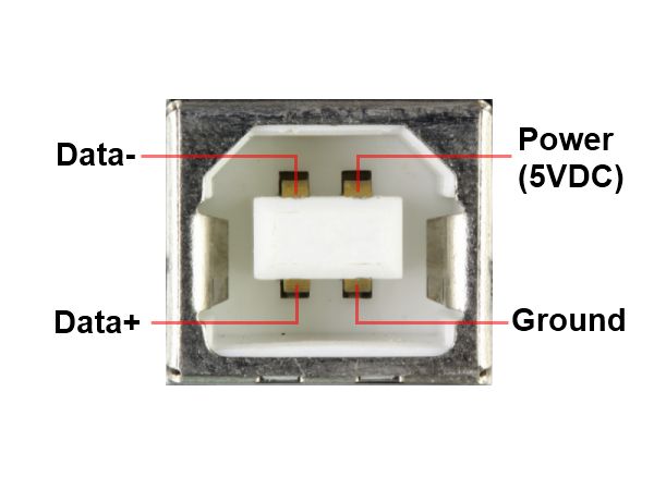
Hooking it up, hardware wise, is a breeze. Attach the NL6621-Y1 3.3V pin to the Arduino 3.3V pin, GND to GND, NL6621-Y1 TXD to Arduino RXD and NL6621-Y1 RXD to Arduino TXD.

Arduino Leonardo connected to an NL6621The NL6621 Wireless ModuleAt first, I used the multiserial mega Arduino script (HERE) to experiment with the AT commands. That script basically takes characters you type in the serial console and sends them to the 2nd serial port and it echos any data coming from the 2nd serial port to the 1st.  I set both serial port BAUD rates to 115200. Sending “AT+HELP” will list all the supported AT commands.

Searching GOOGLE I could not find any information on the AT command set so I took a look at the SerialNet SDK source. Here is a chart showing what I gleaned from that code:

NL6621-Y1 Wireless Module AT commands

Example: Enter DataMODE

============================================================

AT+QUIT

(then telnet to the IP address of the NL6621 on port 8101)

+++ (exits back to CMD Mode)


Example: Scan for Wireless APs
============================================================

AT+WSCANAP=127


Example: Set NL6621-Y1 to be an AP
============================================================

AT+WQSOPT=2,11,3,3,0                     //SOFTAP,11,ccmp,wpa2,disable
AT+WSCAP=nufront,123abcdef,0        //SSID,password,retries
AT+IPCONFIG                                      //Show IP configuration


Example: Set NL6621-Y1 to STATION mode and connect to an AP
============================================================

AT+WQSOPT=0,11,3,3,0                                //Station,11,ccmp,wpa2,disable
AT+WSCAP=your_ap_ssid,yourpassword,5   //SSID,Password,retries
AT+IPCONFIG                                                 //Show IP configuration


Here is an Arduino sketch which sets the wireless options and connects the NL6621-Y1 wireless module to my TP-Link router. Note: If you use this code make sure to change the SSID and PASS variables to match your router!

The NL6621-Y1 Wireless Module Arduino Sketch

One thing I don’t like about the NL6621-Y1 is that it does not have a unique (i.e. official)  MAC address. When you send this:  AT+MAC  the result is +OK=MAC:00:01:02:03:04:05.

Anyway, it will be interesting to see what the open source community comes up with to do with this new wireless chip.
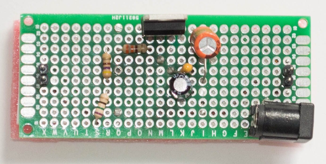
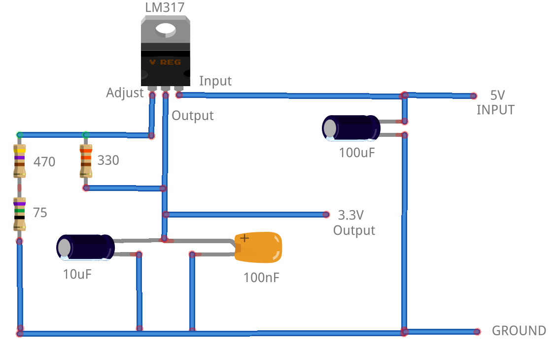
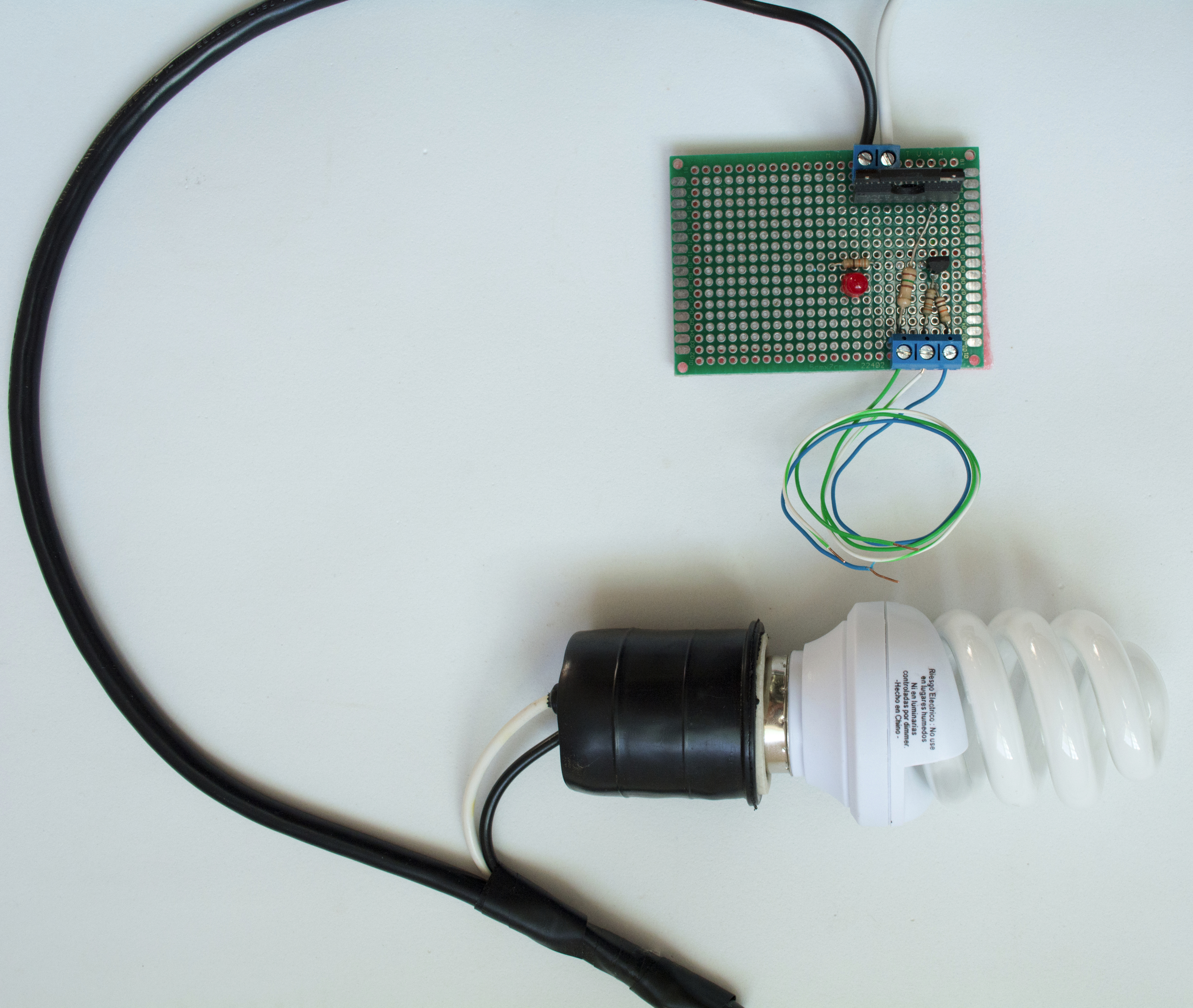
How to Power an LED (Arduino vs. Pinguino)

How to Power an LED (Arduino vs. Pinguino) might seem silly, however, if you take a look at the following graphic, you will hopefully notice something interesting. The Pinguino sources the power to the ‘user’ LED differently that does an Arduino. The Pinguino wiring is represented by the green LED and the Arduino wiring is represented by the red LED.


How to Power an LED (Arduino vs. Pinguino)

How to Power an LED (Arduino vs. Pinguino)

The Arduino powers the LED via a Pin connection versus the Pinguino which sources power to the LED from VCC. So when you write your code to turn on/off the LED notice also the differences. To turn on the Pinguino user LED the Pin is brought LOW via digitalWrite(USERLED,LOW) and turned off via digitalWrite(USERLED,HIGH). Notice this is the opposite to the Arduino code. To turn on the Arduino user LED (on Pin 13 usually) the Pin is brought HIGH via digitalWrite(13,HIGH) and turned off via digitalWrite(13,LOW).

The Pinguino IDE has a ‘built-in’ variable USERLED which references the pin for the user LED on the target Pinguino board. The Pinguino IDE also has a ‘built-in’ toggle() function:

toggle(USERLED);

to do basically the same as:

digitalWrite(USERLED, !digitalRead(USERLED));

If you code and run the standard ‘blink’ sketch or just toggle() you might not notice or care about the difference in wiring, as the LED blinks (regardless of whether it was on or off initially).

I2C Wire Chat Between Two Arduinos

Someone asked me the other day if it was possible to have a ‘chat’ between Arduinos using the I2C Wire library. I came up with  ‘proof of concept’ code called ‘I2C Wire Chat Between Two Arduinos’. Here is the sketch:

I2C Wire Chat Between Two Arduinos

Setup two Arduinos connected by a length of CAT5 cable (you really only need 3 wires). Connect Analog Pins 5 (SCL), 4 (SDA) and Ground as shown in this Fritzing diagram:

I2C Wire Chat Between Two Arduinos

I2C Wire Chat Between Two Arduinos

Make sure each serial port is set to 9600 BAUD and type: #s in one Arduino and #m in the other making sure that ‘New Line’ is sent as the end character. This will put one in slave mode and the other in master mode. Due to the design of the I2C Wire library one has to be master and one slave. Only the master can send data (the slave receives), so it is not simultaneous transmit/receive. Whatever is typed in the master serial console is sent to the slave which displays it on its serial console. To switch back and forth (master <=> slave) just alternate the #s and #m. So you can in essence have a ‘chat’ with the I2C Wire library.

It basically functions the same as a Walkie-talkie radio.

One could even take the sketch further to automatically switch the master to slave and slave to master. For example, when the master is finished it could send a # as the last character which could function as the toggle. I will leave it to the reader to implement this. 😎

Well.. OK.. just so you can see how the code develops, here is the final version with the ‘toggle’ master/slave being the ‘#’ as the last character in the transmission buffer:

I2C Wire Chat Between Two Arduinos  [Final Version]

Over and Out!

Arduino as a Network Monitor

I have set up an Arduino as a Network monitor so I can be silently alerted if a WEB server on the LAN/Internet goes down. In a previous post, here, I show the relay circuit I am using in this sketch to flash a CFL lamp. This sketch also uses the same ENC28J60 module to connect to the LAN/Internet.

Arduino Leonardo and SPI Communications using the ENC28J60 ethernet moduleThe uniqueness of this code is that it uses PING against multiple servers. I tried and tried to get this function using the UIPEthernet library working without success. I finally switched to the EtherCard library and found the solution for PINGing multiple servers. The EtherCard library also solves the problem of the CS Pin on the Arduino Leonardo that I document here. (The EtherCard library allows the code to select which pin will be used for the CS pin.)

There are several interesting things to note about this sketch:

  1. It uses PROGMEM so the IP Addresses are preserved thru each PING loop
  2. The IP address for the ENC28J60 module is dynamically set (the comments show how to switch to a static IP)
  3. MAXCYCLES can be set to re-ping and not alert in case your LAN is not perfect (the device you are pinging might miss a few)
  4. Since this is wired as a temporary setup, I blink the light when the sketch first starts to make sure the wiring is correct
  5. An LCD is used to display the IP address and millisecond PING times (this same info is also displayed to the serial port)

Here is the sketch:

To use it in your environment, change the IP addresses to PING (and number of them) to suit your LAN. Also see the comments to use a static versus dynamic IP address for the monitor itself.

Emergency Phone Call Alert to an Arduino via an Asterisk PBX

Recently, I created this simple circuit (and corresponding code) which makes an emergency phone call alert to an Arduino via an Asterisk PBX.  This project was for someone who needed to be alerted (silently) if someone made an emergency phone call on their Asterisk PBX. By the way, the free and open source Asterisk PBX is a fantastic phone system which can be easily adapted (via custom scripting) to do amazing things!

For this project, the Asterisk dialing plan for the emergency number is set to invoke an AGI script (which in this case was written in python). The AGI python script reads the SIP configuration and creates an Asterisk call file for each SIP peer which puts them all in a conference room. The scenario for this is something like a condominium where there might not be a dedicated person to answer the emergency call, instead everyone in the building (so to speak) is called. The python script also accesses the WEB page of the server running on an Arduino which will rapidly flash an “emergency” light.

I created this simple relay circuit with an S108T02 solid state relay to control the light (CFL). Here is the Fritzing diagram:

S108T02 Relay Fritzing Diagram

You can download the Fritzing code for the circuit here and modify it for your needs. Here is what the circuit looks like when it is built:

S108T02 Relay CircuitEmergency Phone Call Alert to an Arduino via an Asterisk PBX Circuit


Note that the board is about double the size needed so I can add a second relay if future needs require.  🙄

The Arduino code uses the UIPEthernet library to basically create a WEB server. When it is 1st accessed the light is turned on. Access it again and it is turned off. It is a ‘toggle’ so it can be tested from a browser client.  The circuit is attached to an arduino via the pinToToggle value (and also +5V and GND). Additionally the Arduino is connected to an ENC28J60 module for LAN/Internet access. See my previous posts here and here for connecting an Arduino Leonardo to an ENC28J60.

Here is the Arduino code:

The python AGI script:

If you try this out make sure to change the IP addresses in both scripts to match that of your Arduino. Also note that the python AGI script emails someone that the call was made. Check out the bottom part of the AGI script and change the email address to the correct one. (Or comment out that part if you don’t want it to email anyone.)

Do-It-Yourself Pinguino PIC18F4550 Board

I just got a good deal on several PIC18F4550 chips. So, I decided to make a Do-It-Yourself Pinguino PIC18F4550 Board to test them out. The Pinguino boards are based on the same concept as an Arduino. However,  instead of Atmel chips, Microchip PIC® chips are used. All of the Pinguino boards use PIC® chips with on board USB, so the boards are quite easy to access/program. The goal of the Pinguino project is to bring the simplicity of Arduino language to the Microchip PIC® microcontrollers with built-in USB hardware. (Visit the Pinguino project WEB site here.)

The IDE for the Pinguino boards is similar to the Arduino IDE and sketches are also similar, so Arduino users should feel right at home.  Pinguino Hardware and Software, like the Arduino, is all Open Source.

Here is a schematic, a breadboard layout and the DIY Pinguino circuit board I created using the PIC18F4550 microcontroller chip:


PIC18F4550_diagram

Pinguino PIC18F4550 Fritzing Diagram


Do-It-Yourself Pinguino PIC18F4550 Board

Do-It-Yourself Pinguino PIC18F4550 Board

You might notice that in the circuit I built (although not shown in the schematic),  I added a 6-pin ICSP header so I could initially load the bootloader by attaching a PICkit 3 programmer:
PicKit3

6-pin-ICSP-pinoutPic18f4550_icsp

The PICkit 3  plugs nicely into the 6 pin header. The graphic above shows how the ICSP pins of both the PICkit and PIC18F4550 are connected. The bootloader (Version 4) I used can be downloaded here.

Here are the top and back views of the board:

Pinguino_TopPinguino_Bottom

I soldered on  four 10-pin female headers so that connections can be easily made to any pin. I also plugged in two 10-pin male-male headers (un-plugable) so that I can use any jumper wire that I may have around.  The male header PINs between the LEDs are all wired to +5V and the male header PINs at the other end of the board are all wired to GND so there is easy and ample connection to either. I used a type B female USB connector (so it fit the USB printer cables I have so many of).

usb-B-pinout usb2-Bpinout-600


If you’d like the Fritzing diagram for this board you can download it here or the original SVG graphic here. For more information about the Pinguino project visit their Wiki.

Controlling and Monitoring an Arduino Galileo via Node.js

It is very handy to be able to control and monitor things with an Arduino. It is even more handy when you can control and monitor things remotely from wherever you are via the Internet. For arguments sake, lets say we want to both control specific devices we have attached to our Arduino and we want to know when certain events happen (that sensors attached to our Arduino can tell us about).

For the controlling part we could use a WEB application but the WEB is not good for monitoring. This is because the WEB is stateless, it is not a true two way communications system. If we really wanted to use WEB technology, we would need to keep polling (refreshing) from our page which is unnecessary overhead. Yes, we could use an XMLHttpRequest, better know as AJAX, however that too is not the right approach for event monitoring.

Event monitoring in the PC world is normally done via Simple Network Management Protocol (SNMP). That complexity is not needed for something we can implement much more simply. The Arduino Galileo runs Node.js (referred to as node) which makes it very handy and easy to implement a means of both controlling and monitoring events. This is because we can add the socket.io module to node and have true two way communications for both controlling and monitoring. The node server running on the Galileo can monitor for events we want to watch and notify any applications/devices connected to it. The node server can also handle any control requests.

For proof of concept, I coded a node server which uses the mraa module to interface with the Galileo GPIO pins. You can download it here.

Copy it to your Galielo, and extract it with:

tar -xvf galileo_node_server.tar

You will also need to install these node modules (via npm):

npm install http socket.io fs ip mraa

Then start the server via:

node galileo.js

The default port is 8888 which you can  override as an optional parameter if you need to. There is an index.html file that node will send to your browser if you browse to that IP and port. Here is what the WEB (node) page looks like.

Controlling and Monitoring an Arduino Galileo via Node.jsBasically it is a ‘chat’ session. Any commands entered will be sent to the node server and ‘echoed’ back to all applications/devices connected to the server. So you can actually use it as a ‘chat server’ too. Any commands that begin with ‘mraa’ are processed using the mraa module. Then syntax of the command is displayed in case of incorrect parameters.

Additionally, I have coded an Apache Cordova application that you can run on your Android smart phone. You can download it here. The complete Cordova source for the apk can be downloaded here in case you want to make changes. When you install and run the apk, it will first ask you the IP address and port where the node server is running. Then it will connect (via socket.io to the node server) and allow the two way ‘chat’. Here is what the Cordova apk looks like:

Controlling and Monitoring an Arduino Galileo via Node.jsControlling and Monitoring an Arduino Galileo via Node.jsThe next step I have planned is to add sensors for monitoring and add code to the node server to send the monitored data to connected applications/devices. It is interesting to note that this same node.js server code (with the mrra code commented out) will run on a Raspberry Pi. The Cordova app would not need modified (however you might want to change the image/logo from the Galileo to a Raspberry).  😎


Update: 12/28/2015 This project is now on GitHub https://github.com/earlt/galileo-node.git

Load more