4 Character 7 Segment Display

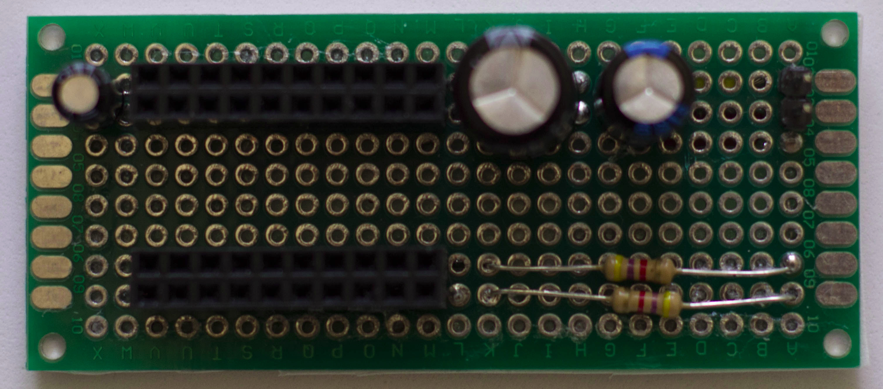
I built another handy circuit to ‘house’ a 4 character 7 segment display. It looks like this:

4 Character 7 Segment Display

Basically it just ‘breaks out’ the 16 pins of the display with two 8 pin female headers. Pins 1-8 are connected to the header at the bottom and pins 9-16 are connected to the header at the top. Note that 6 220 Ohm resistors are needed to protect the LEDs.


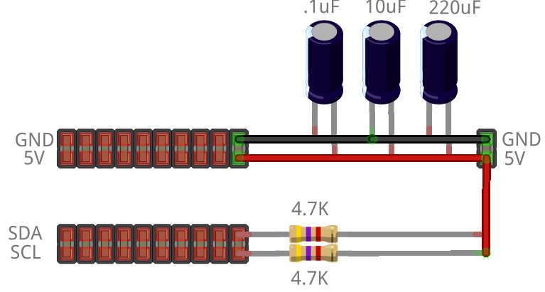
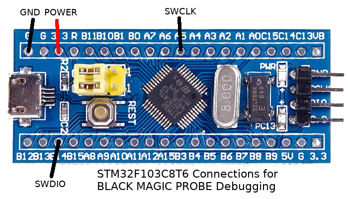
The Fritzing diagram to the right (Download Link) shows which pins select which character (colon or apostrophe) is selected to turn on and thus needs a resistor. The LEDs actually light a bar shape. Each ‘character’ is composed of 7 LEDs (or segments). The image below shows what each of the pins controls.

4 Character 7 Segment Display Pins


The LED pattern is as follows:


7 Segment Display4 Character 7 Segment DisplayFour of these characters go together to be able to display things like time, temperature, voltage, etc.


The technical manual is HERE. The pin functions (1-8 bottom and 9-16 top) are as follows:

Connecting this 4 character 7 segment display to an Arduino is usually done in conjunction with 1 or more  shift registers due to having so many wires. Connecting without the shift register, an arduino looks like it needs a ‘hair cut’ with so many ‘wires’ all over the place.

4 Character 7 Segment Display

4 Character 7 Segment Display


I connected my 4 character 7 segment display circuit with two 74HC595 (shift register IC)  breakout modules. Each 74HC595 module controls 8 pins (1 shift register for the bottom 8 pins and one for the top 8).  With these modules, only 3 wires (besides power and ground) connect to the Arduino.

4 Character 7 Segment Display


Using an Arduino library designed for the 74HC595 shift register makes it easier to control the display. I like this shifter library hosted on GitHub. With it, each pin is easily referenced by number.


Here is a an Arduino sketch I created to display current voltage on the 4 character 7 segment display :

Notice that I created functions to select the specific character to turn on and a function to turn on the LED segments needed to display each number digit. With the shifter library and these functions, you are all set to make something interesting! How about a multimeter?

I2C 2-wire Circuit

My latest project involves collecting data from a number of sensors connected to multiple Arduinos. I2C (or 2-wire) is a perfect fit for this project because I needed an easy way to connect the Arduinos and aggregate the data. With I2C, I can have one Arduino as the master and several other Arduinos as slaves.  To connect the Arduinos together, I created a simple I2C 2-wire Circuit.

Here is the finished product and the wiring diagram:

I2C 2-wire CircuitI2C 2-wire Circuit


You can download the Fritzing source for the diagram HERE. As you can see from the diagram, it allows multiple connections to Power/Ground and multiple connections to SDA / SCL (the two wires used in I2C). SDA (serial data line) is used for sending data and SCL (serial clock line) is used for clocking.  I2C allows for multiple master/slaves. I have one Arduino as the Master and several Arduinos as slaves. I will eventually use a Raspberry PI as the master.

If multiple Arduinos are connected on a breadboard, there can and probably will be some voltage loss. This is especially true when connecting breadboards together and ‘jumpering’ power/ground from one breadboard to another. It is best to supply each breadboard with its own source to power and ground. I built this little testing circuit to get around the power loss problem. Notice that I used 4.7K pull up resistors in this I2C 2-wire circuit. These resistors are needed to ensure the I2C bus works properly.

ESP8266 DIY Programmer Cradle

If you have been reading my posts lately, you will notice that I have been working a lot with the ESP8266 wireless module. To make it easier to work with, I made an ESP8266 DIY Programmer Cradle. Here is what it looks like (without and with the ESP8266 plugged in):

ESP8266 DIY Programmer CradleESP8266 DIY Programmer Cradle


You may notice that I made several of them, some with a 100uF capacitor between Volts and Ground and some without. There are two jumpers, one for GPIO00 and one for GPIO02. When programming the ESP8266, GPIO00 is jumpered to Ground (otherwise it is ‘floating’, i.e., not jumpered). An LED is attached to GPIO02 for testing. Take a look at my MicroPython Web server script mentioned in this post to see how to toggle the LED On/Off. The 6 pin header on the side is connected to a USB to Serial adapter for power and/or programming.

The wiring for the ESP826 and the ‘cradle’ are shown in these graphics:

ESP8266 Wiring ESP8266 DIY Cradle Wiring


Get the Fritzing diagram source HERE. The ESP8266 DIY Programmer Cradle is powered by a USB to Serial Adapter (jumpered to 3.3V) like the one shown below:

USB to Serial ConverterIf you add a power pack (for example, one that is used to charge a phone):

ESP8266 with USB to Serial Converter with Powerbankyou’ll have a portable ESP8266 based wireless module. In any case, with the ESP8266 DIY Programmer Cradle, I have an easy and fast way to plugin, program and test the ESP8266 modules.

MicroPython WebREPL on Android

I created an app (apk) to run MicroPython WebREPL on Android. Imagine you have your ESP8266 (with the MicroPython firmware) in some location where the only access to it is via a wireless connection. If you need to access and change/control it, you will need WebREPL.

Of course, a wireless enabled laptop would get access to WebREPL if you have it installed locally. However, if you are connected to the ESP8266, you might not have internet access to remotely load the WebREPL code.

Alternatively, an Android phone provides the ultimate in portability but has no file system (per se) to store and load the WebREPL code from a browser like the laptop would. You probably could load the WebREPL code in a browser while connected to the internet, then switch over the WiFi to the ESP8266. However, I prefer an app.

So, to make WebREPL available thru an app on Android, I used Apache Cordova to create it. This is a ‘screen shot’ of how it appears on the phone:

MicroPython WebREPL on AndroidIf you are interested in the complete Apache Cordova project code to access the MicroPython WebREPL on Android, download it from HERE. If you are only interested in the apk (app) file, download it from HERE.

The current version of WebREPL uses a no longer supported version of an xterm emulator called term.js  found HERE. While that version works on a PC browser and a browser (like Firefox) in Android, it does not work right inside of an Android app. The keyboard does not function right. So I replaced it with its predecessor called xterm.js found HERE.

If you are interested in the steps I took to create the app, here is what I did:

Those commands will create the basic code for an app. Next, I download and unziped the code from webrepl and xterm.js.

Next, I customized the config.xml to add the MicroPython icon by adding this line:

Then I download the png graphic and  put it in the micropython directory with the name MicroPython.png.

Next, I went to the micropython/www directory and removed everything there. Then I copied over to it these files from where I unzipped the webrepl code:

I renamed webrepl.html to index.html. Next,  I copied over to it (micropython/www) all of the files and directories in the dist directory of the unzipped xterm.js. Then, index.html needed to be changed a bit to use xterm.js vs term.js.

Finally, I built the apk with the command:

and installed it in the phone. After connecting the Android phone wirelessly to the ESP8266 to get an IP address, the MicroPython WebREPL on Android apk is ready to run!

ESP8266 MicroPython Firmware

To enhance the capabilities of the ESP8266 there are various firmware packages available. In my last post, I showed how to install NodeMcu which uses eLua. I am a big fan of the Python programming language, so I was very happy to see a Python version for the ESP8266. The ESP8266 MicroPython Firmware is available from micropython.org. Download it from HERE.

To flash the ESP8266, make sure that GPIOO is  wired to GND. Check the following diagram for the complete wiring:

ESP8266 MicroPython Firmware Flashing(Download the Fritzing source for the wiring diagram HERE.) An interesting post showing how to flash the ESP8266 using an Arduino instead of the USB to serial converter (used in the graphic above) can be found HERE.

To flash the ESP8266 MicroPython Firmware, make sure that the flash tool (esptool.py) is installed (or if installed, is up to date):

Here are the commands to flash the ESP8266 MicroPython Firmware:

Version 1.9.1 was the current version when I wrote this post, so the flash file name will vary. Once the firmware is loaded, open a serial terminal program like picocom via:

You might have to ‘hit enter’ a few times to get to the >>> MicroPython REPL prompt.To verify the flash use these commands:

The result should be ‘True’ if flash is OK. Even so, I still had problems when I flashed some of my ESP8266 modules. The problem was resolved by ensuring a stable/good power source and letting esptool.py use its default baud rate to do the flashing.

A WEB accessible REPL prompt is also possible once installed/configured  via:

from the serial connection. Download the WebBREPL code from HERE. This comes in quite handy to connect and enter commands when the only access to the ESP8266 is wireless. If you don’t have a ‘local’ copy of WebREPL to run, it is hosted here: micropython.org/webrepl. Note: Once that code is loaded in your browser, it will connect via websocket to your ESP8266 module.

To show what can be done with ESP8266 MicroPython Firmware, I wrote a WEB server script to toggle pin 2 (GPIO2). This is basically the same functionality as the Lua script in my previous post but this one is coded in Python. Download it from HERE.

For more information on the specifics of MicroPython on the ESP8266, consult the Documentation HERE.

ESP8266 Custom Firmware

If you would like to go beyond the basic features in the ‘default’ ESP8266  firmware, it is possible (and relatively easy) to create your own ESP8266 custom firmware.

ESP8266 Custom FirmwareWith ESP8266 custom firmware, your possibilities for interaction with connected devices are almost endless.

The reason why is that you can now connect pins on the ESP8266 to other devices and control those devices ‘programatically’. This is possible due to the custom firmware using the LUA programming language (specifically embedded LUA or eLUA). The team at nodemcu.com have developed an ESP8266 based IOT module called NodeMcu and open source firmware for it. You can see examples of what can be done with LUA on their main WEB page. Their firmware (available on Github HERE) can be FLASHed on any ESP8266 Wifi SOC.

I am using an ESP8266-01 module (as seen in the above picture). It only has two GPIO pins available, however, that is sufficient for what I need. Other ESP8266 models (like the NodeMcu) have a lot more pins broken out for use.

The documentation for the NodeMCU firmware is HERE. There is a ‘cloud’ (i.e. WEB) based service to build a custom firmware image HERE. However, I prefer to experiment on my own, so I installed the development tools locally on my Fedora Linux system. Here is how I did it:

First, make sure all the Fedora Linux prerequisites are installed:

Next, make sure that the flash tool (esptool.py) is installed (or if installed, is up to date):

Next install the development toolchain for the ESP8266:

That will take a while and let you know the PATH to export so the next step can invoke the toolchain correctly. Next, install the NodeMcu firmware:

Next, read the build documentation to see how you want to customize the options and what ESP8266 function modules you want to include. After you customize:

This will take a while and then produce two bin images in the bin directory:

0x00000.bin and 0x10000.bin

Now you are ready to flash those files into your ESP8266 module. Make sure the ESP8266 is in flash mode via GPIO00 pulled low (normal GPIO00 is high or floating). Here is how it should be wired:

ESP8266 Wired for Flashing(The Fritzing diagram source is HERE.) Then flash the ESP8266 with these commands:

An alternative is to combine (aggregate) the binary images into one file. To make the aggregated file, here is a python script to automate it:

To flash that aggregated file use these commands:

The ESP8266 can then be accessed by a serial connection. I recommend getting the ESPlorer developer IDE found HERE. It makes coding and uploading your LUA code very easy. Here is a screenshot of ESPlorer:

ESPlorer Screen Shot (ESP8266 IDE tool)There are sample LUA scripts in the nodemcu-firmware-master directory for you to experiment with or exercise your LUA skills and develop your own.

For example, here are the commands to setup the ESP8266 as an Access Point and set its SSID and Password:

HERE is an example LUA WEB server script to toggle PIN 4 (GPIO2) from a WEB page. It is called init.lua so that when the ESP8266 is powered on it will run that script automatically. Of course just toggling a PIN is not so useful 🙄 so you will want to attach it to something like a relay to turn something on or off.

For the latest information on this whole process, consult the NodeMcu documentation HERE.

Best Kept Secret

Yes, it is an ambiguous topic. No, I don’t think it should be hidden, however, the fact that this topic does not seem to garner much press could mean it has been a best kept secret.

The “best kept secret” is the programming language Forth. For reference, take a look at “A  Beginner’s Guide to Forth” from J.V. Noble.

Forth is specially useful on microcontrollers due to its ‘small’ size. ‘Mecrisp Stellaris’ from Matthias Koch is a case in point. I have been experimenting with it on my STM32F103C8T6 boards and am amazed at what it can do.

Forth is quite different than other programming languages. When loaded into a microcontroller, It interacts via a serial/usb ‘console’ and, to me, is like an Operating System but better!  It’s an ‘applications programmer’ dream environment uncluttered by a ‘systems programmer’ idea of what should be there. If you read the history of Forth and thus the history of Chuck Moore (the inventor of Forth) you will better see what I mean.

I think Jean-Claude Wippler (jeelabs.org)  understates the usefulness in his article titled ‘F103 + USB = Swiss Army Knife’.  Jean-Claude has enhanced (Mecrisp Stellaris) Forth with lots of code/examples. Take a look at his artcile about it HERE. He also has a communications program (written in ‘GO‘) called Folie which makes it easier to interact with Forth.

To install it on my Fedora Linux system, I ran this:

Then run it via:

and it will prompt you for the serial port.

I have also updated my Python serial program script to communicate with Forth as an alternative to Folie. Here is the code:

Inspired by the built in commands that Folie has to interact with Mecrisp Stellaris Forth I added added some to  my script. Use: !help to list them.

If you are new to Forth it may take some getting used to. It relies on the stack to store everything and thus uses ‘reverse polish notation‘. This way of thinking is different that ‘traditional’ languages such as C or Python, etc.  and is perhaps why some programmers get frustrated and give up.

So, is Forth ‘hidden’ due to frustration and lack of programmers using it or is it just not widely marketed? In any case, why not give it a try? If you need more to convince you, take a look at Elliot Williams’ article called Forth: The Hacker’s Language on Hackaday.com.

How to convert an STM32F103C8T6 into a Black Magic Probe

There are several tutorials on the internet showing how to convert an STM32F103C8T6 into a Black Magic Probe. Unfortunately, none of them worked for me. So, I decided to write this post in case others run into the same problem as I did. The problem I ran into was the memory size of the STM32F103C8T6 chip I am using. It reports that it only has 64K of flash. The Black Magic Probe software is a bit larger than 64K so the utilities report there is not enough memory and stop.  Decoding Preview Changes (opens in a new tab)‘STM32F103C8T6’

STM32F103C8T6
STM STMicroelectronics – Vendor
32 32-bit, ARM series
F103 model, ‘F1’ = ARM Cortex M3
C 48-pins
8 64 KB flash memory
T LQFP package type
6 temperature range -40..+85 °C

we see that it is only supposed to have 64K, however, it probably has 128K. Mine does!  So, with a bit of ‘trickery’, we can make it work.

There are possibly three different ways to connect and interface with the STM32F103C8T6 board:

  1. Serial port
  2. USB
  3. JTAG / SWD

The utility software (listed below) varies as to what interface it uses. To get my STM32F103C8T6 module to work with the utility I need, I used an ST-LINK programmer which attaches to the SWDCLK/SWDIO/PWR/GND pins.

How to convert an STM32F103C8T6 into a Black Magic Probe Here is a list and some information about the software tools (utilities) you will run across when reading articles about programming the STM32F103C8T6. Incidentally,  I run a Linux distribution called ‘Fedora‘. If you are running a different Linux distribution, you will need to run your appropriate package installer rather than the one (dnf) Fedora uses.

For installing and compiling some of these utilites, you will need git, cmake and the ‘normal’ set of development tools installed. If you do any development work these tools should already be installed.

Here is the command to install all the needed development (C compiler) tools for the ARM processor:

Many of the useful utilities are coded in Python and need the Python serial module. Here is how to install it:

Here is a list of the utilities:

stm32flash
Open source cross platform flash program for the STM32 ARM microcontrollers using the built-in ST serial bootloader over UART or I2C

stm32loader.py
Python script which talks to the STM32 bootloader (via the serial port) to upload and download firmware.

stlink
Open source version of the STMicroelectronics Stlink Tools

dfu-util
DFU is intended to download and upload firmware to/from devices connected over USB.

OpenOCD
Open On-Chip Debugger

Black Magic Probe
In-application debugging tool for embedded microprocessors.

I eventually installed all of these utilities, however to create a “Black Magic Probe Clone” I really only needed stlink, OpenOCD and the Black Magic Probe software. So, here is how to convert an STM32F103C8T6 into a Black Magic Probe:

I installed OpenOCD via:

This step (using OpenOCD to unlock the code protection of the board that will become your new Black Magic Probe) may not be needed but just in case, here it is:

Next, I installed the stlink utilities globally via:

Then, to create the Black Magic Probe Software:

Make sure you are in the black magic probe src directory. Then erase memory and flash the black magic DFU and software ‘bin’ files via:

Note: Here is where the ‘trickery’ comes in. Using the parameter –flash=0x20000 we can override the reported 64K and specify 128K. Now you can unplug the STLINK programmer and plug in the usb port. You should then see two enumerated ports (probably /dev/ttyACM0 and /dev/ttyACM1).

The Black Magic Probe supports both JTAG/SWD and Serial/UART debugging simultaneously.  The 1st port (/dev/ttyACM0) is for JTAG/SWD (GDB server) and the second port (/dev/ttyACM1) is a serial UART.  Here are the Pin references for the Target and the Debugger (i.e.  the Black Magic Probe):

To make it easier, next time I wanted to do this, I created a Python script which runs those needed commands. Additionally, it combines blackmagic_dfu.bin and blackmagic.bin into one bin file called bmp.bin. The script allso runs stlink to dump the memory (after flashing) to compare it with the original to make sure the flash worked ok.

Here is the Python script (it needs to run from the blackmagic probe src directory):

If you don’t have an STLINK programmer, there is an alternate method to create and flash the bmp.bin file. Create the bmp.bin file with this Python script:

STM32FLASH can be used with a USB to serial converter to flash the bmp.bin file via the following command:

Make sure to replace the /dev/ttyUSB0 with your specific port.

To test your new ‘Black Magic Probe clone’, attach it to a target:

STM32F103C8T6 as a BlackMagic ProbeThen run:

Further documentation on GDB (The GNU Project Debugger) can be found HERE.

SSD1306 OLED Displays

For many Arduino projects, there is a need to display information graphically or display more text than what fits on a 16×2 LCD. For that need, consider using SSD1306 OLED Displays.

SSD1306 refers to the controller or driver chip for the display. OLED or  Organic Light Emitting Diodes refers to the dot-matrix graphic display system. These displays attach using SPI or I2C thus using less connecting pins versus an LCD.

Here is how to hook-up a I2C SSD1306 OLED display to an Arduino UNO:

SSD1306 OLED Displays (attached to an Arduino UNO)

The Fritzing diagram source is here. The OLED fritzing part is here.

To write Arduino code for SSD1306 OLED displays, we need to find the I2C address. The MiniPirate sketch I wrote about here can be used to find it. Also there is an I2C scanner sketch here. There are also two libraries needed to control the OLED display:

Adafruit SSD1306 Library   Adafruit GFX Library

Once those libraries are added and you have the I2C address, try the following sketch:

The I2C address for my OLED Display is 0x3C so the display.begin code is:

   display.begin(SSD1306_SWITCHCAPVCC, 0x3C);

You will need to change the 0x3C to the address of your display. Also, the library does not detect the resolution of the display. The sample sketches that come with the SSD1306 library mention how to change the library to match the resolution of your display. Basically, look at the code in Adafruit_SSD1306.h and find the lines which define the resolution. Uncomment the one you need and comment the rest. Here is what that code looks like for the OLED display I have:

Here is what the OLED Display looks like when displaying text:

OLED Display attached to an Arduino NanoOLED Display attached to an Arduino Nano

ARM Cortex M3 STM32F103C8T6

It’s amazing what you can get in a microcontroller board these days for just over $2. For example, just search ebay.com or alibaba.com for the key word ‘STM32F103C8T6’.  You will see the links to an ARM Cortex M3 STM32F103C8T6 development board for just over $2 US including shipping (usually from China, so it may take a bit to arrive). If you want it faster (if you live in the U.S.), you can order from US suppliers but expect to pay more.

The board, sometimes called the ‘blue pill‘ (a reference to the 2016 film “The Matrix”) looks like this:

ARM Cortex M3 STM32F103C8T6 ARM processors are based on the RISC (reduced instruction set computer) architecture developed by Advanced RISC Machines (ARM). ARM licenses the technology to manufacturers such as STMicroelectronics which makes the processor on this particular board. The processor data sheet can be downloaded HERE. The reference manual is HERE. The programming manual is HERE. The system memory boot mode application note is HERE.

Briefly, here are the specifications:

  • 32-bit ARM Cortex-M3 processor 72 MHz
  • 64 kB flash memory, 20 kB SRAM
  • USB and CAN controllers
  • 32 kHz crystal for RTC
  • dual 1 us A/D converter, DMA controller
  • SPI, UART, I2C
  • Serial wire debug (SWD) & JTAG interfaces
  • 7 timers

You might also see this ARM Cortex M3 STM32F103C8T6 board advertised as an ‘Arduino’ board. Although it is not really an Arduino, the guys at stm32duino.com have developed a means to integrate it into the Arduino IDE. They have also ported some of the Arudino libraries to support this board. However, do not expect every library supported for an Arduino to work on this processor. For more information on what works and what might not, check out the stm32duino forum HERE.

This board is easily programmed with a ‘standard’ USB to Serial converter from FTDI or SILABS or an ST-LINK V2 in-circuit debugger and programmer from STMicroelectronics. These devices communicate with the bootloader which is stored in the internal boot ROM memory (system memory) of STM32 devices. This bootloader is programmed by STMicroelectronics during production and its main purpose is to download the application program to internal FLASH memory.

STLINK V2 Programmer / Debugger


My preference is the ST-LINK V2 since it also functions as an in-circuit debugger. OPENOCD.org fully supports the ST-LINK V2 and the STM32F103C8T6 board. OCD (On Chip Debugging) comes in quite handy to diagnose those ‘complexities’ 😎 in your code.


To program it, you might need to change the BOOT0 and/or BOOT1 jumpers as those pins select how the STM32F103C8T6 starts.


BOOT1 BOOT0 Boot mode
X 0 User Flash memory
0 1 System memory (bootloader)
1 1 Embedded SRAM


Here is what the STM32F103C8T6 looks like attached to an ST-LINK V2 programmer and a SILABS CP2102 USB – Serial converter:

STM32F103C8T6 with ST-LINK V2STM32F103C8T6 with CP2102

Load more