The Arduino Command Line Interface (CLI)

The Arduino folks just came out with the Arduino Command Line Interface (CLI) :

A while back, I wrote about the  Arduino-Builder which is what the Arduino IDE invokes behind the scenes to compile the sketch. (That post is here.) Now, with the Arduino Command Line Interface, everything that can be done from the IDE can now be done on the command line.

The Arduino Command Line Interface can be downloaded from here. By the way, it is also written in the Go language.

I downloaded the file for my system (Linux 64 bit):

Extracted it:

and moved it to an easier name:

I tried it out and got it working OK for the BluePill but had to make some changes to the boards.txt configuration file.

Here is how I got it working for both the Arduino Uno and  the BluePill (STM32F103C8T6):

Create these directories first (the are needed and not created if they don’t exist):

Create a basic config file since it will need to be modified to add the BluePill info:

Edit the .cli-config.yml and add these lines at the end:

Next, create a basic test sketch (and optionally edit it):

Next, create the index json files via:

Optionally look and see what boards are available to install:

Then install the stm32duino files for the BluePill:

Optionally install the core files for the Arduino Uno (etc.):

You can see a list of the installed boards via:

If you try and compile the test sketch now via:

You will see a bunch of errors, so you will need to edit the boards.txt file:

To eliminate the errors, change some of the genericSTM32F103C lines with  the string genericSTM32F103C.menu….build. in them to just genericSTM32F103C.build. lines. Make sure there are no duplicates. (The .menu. lines are for selections in the Arduino IDE.)

Once all the correct options are fixed in the boards.txt config file, the sketch should compile fine via:

To see if the arduino-cli recognizes your attached BluePill (or other Arduino), run:

To upload the sketch:

Libraries can be found with a search:

And installed via:

……………………….

At no time did my fingers leave the keyboard… I like the cli !

STM32F103C8T6 DIY Programming Cradle

I recently created an STM32F103C8T6 DIY programming cradle. Here is what it looks like:

STM32F103C8T6 DIY Programming CradleIt comes in handy when you need to program a bunch of STM32F103C8T6s. (Note: I made a similar ‘cradle’ for programming bunches of ESP8266s’.  Read about that here.)

A standard USB to serial converter is attached to the 6 pin header shown on the right side. Here are some pictures. When the STM32F103C8T6 is ‘plugged in’:

STM32F103C8T6 DIY Programming CradleWhen it is attached to a USB / Serial converter:

STM32F103C8T6 DIY Programming Cradle

This Fritzing graphic shows how the connections are made from the USB to serial converter to the STM32F103C8T6:

STM32F103C8T6 Serial Connections

Download the Fritzing source here.

Push a Button and Play a Video

To motivate and engage sales people, have a big red button to push when a sale is made. They push a button and play a video. Something fun! Add flashing lights for extra effect!

Here are two different means to accomplish this. One solution involves an Arduino UNO serially attached to a PC running  the Windows OS. The other solution is just a Raspberry Pi running OSMC. OSMC basically turns a Raspberry Pi into an entertainment system.

A large screen can be attached to either the Raspberry Pi or a PC to display the video.  A Raspberry PI has GPIO pins which allow it to connect to the outside world. This makes it a standalone solution for this application. A normal PC has no such connections, so that is why something like the Arduino is needed.

The Arduino UNO connects to the PC via a USB to serial cable. This is how the Arduino can be wired to a button:

Push a button and play a videoDownload the fritzing source HERE.  Note: The wiring is basically the same for a larger big red button which would be easier to push (and more fun!)

Notice how the standard 4 pin push button is wired:

4 Pin ButtonWhen the button is pushed,  all four pins are connected. This is the Arduino sketch for monitoring the button push:

The  Arduino communicates serially to a Python script. The Python script, when notified of a button push, will start the video player to play the video. Here is the script:

Since that python script was designed to run on a Windows PC, VLC and Python need to be installed for it to work. The command to run VLC will need to be modified to the URL or file for the specific video to play.

The alternative solution to “Push a Button and Play a Video” is just a Raspberry Pi.  After installing the OSMC distribution,  use these commands to install the prerequisite software :

The prerequisite software is needed to allow a Python script to access the GPIO pins and interface with OSMC.  Next, wire the Raspberry Pi  to the button as show here:

Push a Button and Play a Video

Download the fritzing source HERE. A Python script (running on the Raspberry Pi) is used to monitor for the button push and run the video:

The Raspberry Pi running OSMC uses the xbmc_json python library to control  the native OSMC video player. The command to open the player and run the video will need to be modified to the URL or file for the specific video to play.

Which ever solution you choose, push a button and play a video! Fun!

Pulse Width Modulation

MicroControllers are digital devices and usually do not have built in digital to analog converters (or DACs) to output an analog signal. Some, however, do have analog input. For digital output, the voltage is one of two values. Output voltage is either 0 volts or near equal to the voltage source (‘off’ or ‘on’). Using a technique called pulse width modulation (or PWM), a microcontroller can create a ‘simulated’ analog output voltage.

Pulse width modulation turns the output on and off, each with set times at high frequencies to achieve an analog voltage. If you are unfamiliar with pulse width modulation, there are many tutorials on the internet. (Click HERE to search Google for PWM. An excellent one for the Arduino is HERE.)

Here is a short video of pulse width modulation on a PIC12F675 captured on an MSO-19 oscilloscope:


As can be seen in the video, the duty cycle (ratio of ‘on’ versus ‘off’)  goes back and forth from 100% to 0%.

Here is the MPLAB XC8 C source code for creating that PWM signal on a PIC12F675:

The original code was generated with my PIC Timer0 Code Generator and Calculator for a PIC12F675:

Pulse Width Modulation on a PIC12F675

and then modified to vary the duty cycle. An MSO-19 oscilloscope was used to capture the  PWM signal. If LEDs were placed on the pins of the PIC12F675, they would be seen gradually going from bright to dim and back again to bright.


Using pulse width modulation, an output voltage can be produced anywhere between zero volts and the source voltage. Its simply a matter of math!  For example, if  the source voltage is 5 volts,  to create a 2.5 volt output,  the output pin would be ‘on’ half of the time and ‘off’ half of the time.   (5  ÷ 2 = 2.5)  Of course the frequency of the switching cycle has to be significant.

PIC Timer0 Code Generator and Calculator

I needed an easy way to calculate Microchip PIC timer 0 values, so I created the PIC Timer0 Code Generator and Calculator.  If you are not familiar with PIC timers, there is a handy tutorial HERE.

The calculator part, is a spreadsheet which calculates the timings and timer 0 frequency counter needed, given the  required timer (delay). The code generator part, is a Python script which generates the C source code for the PIC microcontroller XC8 compiler.

Here is what the spreadsheet looks like:

Basically, the required timer (i.e. delay) in seconds is specified along with the clock source in Mhz and the prescaler. Optionally a value can be specified for the TMR0 preload to adjust the timing.  All the other values are automatically calculated.  From the example, a 1 second delay is specified with a clock of 4Mhz,  prescaler is 32 and preload is 6.  The calculations show that 125 timer 0 interrupts will take 1 second.

The spreadsheet calculator can be downloaded from HERE.

In these examples, I use the PIC12F675 programmed with a PicKit2 programmer:

PIC Timer0 Code Generator and CalculatorPIC12F675


However, even though I use a PIC12F675 for the PIC Timer0 Code Generator and Calculator, it can easily be adapted to any other PIC microcontroller which needs timer 0 calculations. Actually, the spreadsheet part works works for any PIC since it does not generate code. The Python script, which generates code, would only need minor changes for other PIC microcontrollers.

Here is the Python script (gentimer0.py) which generates the C code:

Here is the command to run it:

and here is the resultant output:

The source is complied (via the Microchip XC8 compiler) with this command:

Then use the PicKit2 programmer:

PICKit2 Clone Programmerwith the command:

to send it to the chip.
PIC Timer0 Code Generator and CalculatorNotice, that /opt/microchip/ is where I have installed he XC8 compiler and the PicKit2 software (pk2cmd).  If you have an LED on GPIO pin4, it will blink every 1 second. Basically with this code generator, one has a starting point template to add to. The comments in the code show where to put code to make it more useful.

Controlling Things Based on Light Intensity

A PhotoCell or LDR (Light Dependent Resistor), used in a circuit, allows controlling things based on light intensity.

PhotoCell

PhotoCell / LDR (Light Dependent Resistor)

Here is a circuit showing how to wire an LDR and demonstrates how controlling things based on light intensity is possible with a little help from a microcontroller.

PIC12F683 with LDR

Controlling Things Based on Light Intensity

The thing being controlled in this circuit is simply an LED which turns On or Off. However, it could just as easily be a relay to control some other device. (Get the Fritzing source HERE for the above circuit graphic).

An analog value of the voltage which varies with light intensity can be read by a microcontroller. In this circuit, a PIC12F683 microcontroller is used. Based on that value, other circuitry can be controlled (i.e. turned On or Off).

Here is the MPLAB X IDE C source code for the PIC12F683 in the circuit shown above.

The analog value varies from 0 to 1024 with 0 being no voltage and 1024 being max voltage. The code shows turning on the LED if at least 1/2 of the voltage  (1/2 of 1024 = 512) is being passed by the LDR. Since the source voltage is 5V,  1/2 of it would be 2.5 volts.  Depending on the application for this sort of circuit, some experimentation can be done to determine the optimum value for when to turn something On/Off.

The data sheet for the PIC12F683 is HERE.  It is essential reading in order to understand how to write code for the chip. Native C coding (using the MPLAB X IDE) for PIC microcontrollers is a bit harder than the ‘sheltered’ environment of the Arduino IDE.

Yes, you can do this sort of thing with an Arduino (and the code would be easier to develop) but at a higher component cost. The components in this sample circuit are minimal, small and low cost.

How to keep an ENC28J60 Module from Freezing

The ENC28J60 module is good for attaching an Arduino to a LAN or the Internet. The one real problem in doing so is how to keep an ENC28J60 module from freezing. No, not temperature wise ! 🙄  (‘Freezing’ in the sense of locking up, stop working, etc.)

How to keep an ENC28J60 Module from Freezing

ENC28J60 LAN Module

There are many Ethernet  arduino libraries for the ENC28J60 module, however,  I am using the UIPEthernet library from HERE. It is updated from the original Ethernet and follow on UIPEthernet libraries. Documentation on the Ethernet library can be found HERE along with sample code. Note: The UIPEthernet library I am using fully supports all the documented functions from the original library.

There are various ERRATA on the ENC28J60, however, the current versions of the UIPEthernet  library address those issues. This library also supports the STM32F103C8T6. Usually one would think that such ‘lockup’ or ‘freezing’ problems are related to power problems. That problem is not an issue here, it is taken care of by testing with different good power sources and lots of capacitance.

I have the most trouble when I attach an STM32F103C8T6  to the ENC28J60 module.

ARM Cortex M3 STM32F103C8T6

STM32F103C8T6

I seem to have the least problems when I attach an Arduino UNO to it.

Arduino UNO

Arduino UNO

I think that perhaps the extra speed of the STM32F103C8T6 enhances the problem. In the main loop() code, the library function checks on the ENC28J60 and perhaps due to the faster speed of the STM32F103C8T6 there is something going on that affects the ENC28J60.

Another, less know issue, is the need to occasionally call the library function maintain(). If one looks at the documentation, it seems maintain() is only used to renew a DHCP lease. Further research will show that this function call is needed, periodically, if connected to an ENC28J60.  I found that there are fewer ‘freezing’ problems when calling that function in the main loop() code, however, they still occasionally happen.

The best approach to fully solving the issue is to somehow check the status of the ENC28J60 and reset it if it is ‘frozen’. Fortunately, the code for that is available HERE.

This is my sample WEB server code which shows how to keep an ENC28J60 module from freezing by implementing that checking of the ENC28J60.  It also shows the use of the maintain() function and the use of the STM32F103C8T6 watch dog timer. I use the watch dog timer to make sure the mictocontroller running the code to control the ENC28J60 is not somehow locked up (‘frozen’).

Here is the code:

From the ASCII chart in the comments at the top of the code, one can see how the STM32F103C8T6 is wired to the ENC28J60.  One thing to note, is that the RESET of the ENC28J60 is accomplished via its RESET pin rather than by calling the Enc28J60.init() function.  This does a hardware reset and seems to work in all lockup cases.

Switching 12V from a 5V Arduino

I built a circuit to allow switching 12V from a 5V Arduino. Here is the wiring diagram and a picture of the actual circuit:

Switch 12V from 5V ArduinoSwitching 12V from a 5V Arduino


Get the Fritzing source HERE.  The side with two connections attaches to the 12V device being switched ON/OFF. The side with three  connectors,  connects to the 12V source and Ground. It also connects to an Arduino PIN to do the ON/OFF switching.

The actual circuit (pictured above) is doubled and can handle switching two 12V devices.  A PC power supply (converted to a ‘bench power supply’) can be used to power the Arduino and the 12V devices,

You can hook up a PC power supply and make a bench power supply with an adapter. That adapter easily attaches to the power supply and breaks out the 12V, Ground, 5V and 3.3V sources. Pictured below is an example of such an adapter:
PC Bench Power Supply AdaptorThe circuit switching 12V from a 5V Arduino  comes in handy for a number of things. I am using it to turn on a 12V Emergency Alarm.  Here are the two types (siren and siren with strobe) that I am using. They both work with 12V and Ground.

Switching 12V from a 5V ArduinoSwitching 12V from a 5V Arduino


This circuit switching 12V from a 5V Arduino is part of a much larger home/office alarm system project I am working on.

Decoding an ESP8266 Firmware Image

I recently coded a Python script for Decoding an ESP8266 Firmware Image. It’s the first part of my quest to create a Linux tool for creating a single flash image.

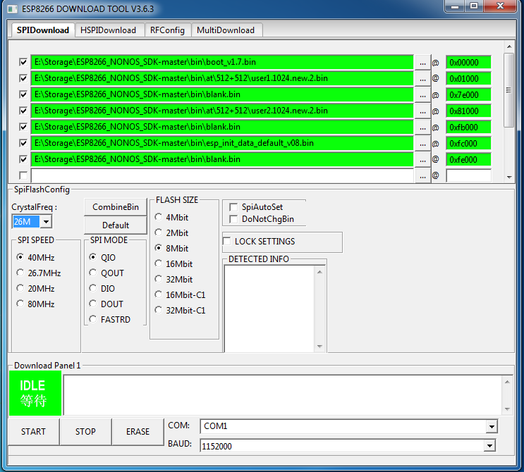
More specifically, the script will decode a single binary image or a ‘combined’ image. A combined image (single flash image) can be created with the flash download tool from Expressif. (Exressif is the company which makes the ESP8266.)  However, that download tool only runs on Windows. Here is what the Expressif Flash Tool looks like:


ESP8266 Flash Tool on Windows

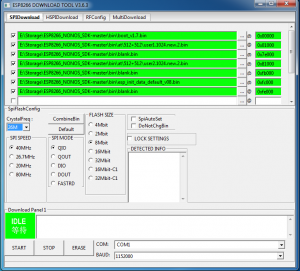
Notice, the ‘CombineBin’ button. It is used to create a single binary image from the multiple files (‘segments’). In that image you can see seven files (the current SDK 2.1.0 files as of this post date) listed and the addresses to load them . I used the ‘CombineBin’ button and created a single binary image called sdk-2.1.0.bin. (The default file name it creates is called target.bin.)

I run Linux. and the recommend ESP8266 tool for it is esptool.py. The esptool script, however, does not have a option to create a single combined image. It may have that feature as an enhancement at some future time. Hence, my quest, to develop a Linux tool to create a single flash image.

I like to keep my ESP8266 firmware current. To flash the latest SDK, I use this script:

While that works fine, I think it would be more efficient to create a single combined image to flash. Especially since I have a number of ESP8266 modules to flash. The single image (sdk-2.1.0.bin created from the windows tool) can be flashed as follows:

To create a tool to combine all the ‘single’ images into one, one needs to know the format of the single images and the format of the ‘combined’ image.

Espressif has a brief document (HERE), describing the firmware image format. However, that document does not fully cover what is need to decode a combined image. Also, it does not cover all of the single image ‘formats’. Esptool.py has an image_info command, however, it only works on single modules. It does not work on combined modules.

In my ‘reverse engineering’ attempt at Decoding an ESP8266 Firmware Image, I created this Python script called esp8266_parse_bin.py. Here is the code:

Esp8266_parse_bin.py can be used to decode any of the single modules that comprise the combined sdk-2.1.0.bin image or it can be used to decode the ‘combined’ image.

When it is used to decode the combined sdk-2.1.0.bin image via:

Here is what the output looks like:

From that output, one can see where (address) and how each of the single images are placed in the ‘combined’ image.  Now that the combined image format is known, a script can be coded to create it from the individual files.

12V to 5V Sensor Circuit

A number of sensors are powered via 12 Volts. Some, however, need 5 Volts.  To power a remote DHT11 temperature sensor, I created a 12V to 5V sensor circuit.

This is the wiring diagram:

12V to 5V Sensor Circuit

Get the Fritzing code for it HERE.

DHT11

DHT11


The DHT11 needs 5 volts,  ground and data. It plugs into the 12V to 5V sensor circuit via a 4 pin header slot. Notice there is a 10K pull-up resistor connected to data.

Here is what the circuit looks like with and without the DHT11 plugged in:

12V to 5V Sensor Circuit Side View12V to 5V Sensor Circuit with DHT11

This type of circuit comes in handy for a larger project such as an alarm or monitoring system where sensors are some distance away from the main monitoring device such as an Arduino.  For longer distance cable runs, Cat 5  cable is used which has 8 wires.  Three wires can be twisted together for 12 volts. Three wires can be twisted together for ground and the remaining 2 wires can be twisted together for data.  The multiple wires together increases the ‘wire size‘ and overcomes signal loss and interference in most cases.

Load more