Hacking your Car with an Arduino and a CAN BUS Module

Your car is full of electronic devices. In fact, General Motors is one of the largest computer manufacturers due to its need of microcomputers in cars that it makes.  If you have an interest in what goes on with your cars’ electronics, you might want to invest some time hacking your car with an Arduino and a CAN BUS Module.

Quoting from the CAN BUS Wikipedia article:

‘A Controller Area Network (CAN bus) is a vehicle bus standard designed to allow microcontrollers and devices to communicate with each other in applications without a host computer. It is a message-based protocol, designed originally for multiplex electrical wiring within automobiles, but is also used in many other contexts.’

A modern car has many ECUs (or Electronic Control Units). These ‘computers’ send and receive information over the cars’ CAN BUS. De-coding that information can give you a wealth of information about the workings of your car.

The CAN BUS on your vehicle can be accessed from the OBD II connector.  I wrote about OBD II and diagnosing car problems in an earlier post here. If you are wondering if your car has an OBD II port, it probably does. All cars and light trucks built and sold in the United States after January 1, 1996 were required to be OBD II equipped.

The OBD II connector looks like this:

OBD II Connector

 
PIN DESCRIPTION PIN DESCRIPTION
1 Vendor Option 9 Vendor Option
2 J1850 Bus + 10 J1850 Bus
3 Vendor Option 11 Vendor Option
4 Chassis Ground 12 Vendor Option
5 Signal Ground 13 Vendor Option
6 CAN (J-2234) High 14 CAN (J-2234) Low
7 ISO 9141-2 K-Line 15 ISO 9141-2 Low
8 Vendor Option 16 Battery Power


Note: Pins 6 and 14 are specifically for the CAN BUS.

The CAN BUS module that I am using looks like this:

CAN BUS Module

The module has a seven pin connector for attachment to the Arduino . Two pins are used for +5V (power) and GND. The other five (MISO, MOSI, CS, SCK, INT) are for the SPI interface.. The J1 connector is a jumper for 120Ohm termination of the bus. (I have that jumper connected on both modules in my test environment shown below.) The CAN BUS is connected to the module either by the screw terminals or the two pin header behind the screw terminals. Note that one is labeled H for High and the other is L for Low.

Before hacking your car with an Arduino and a CAN BUS module, you may want to do what I did. I used two modules connected together to form a two node test CAN BUS network. That setup looked like this:

Hacking your Car with an Arduino and a CAN BUS Module

Basically, a double wire connects the CAN BUS High/Low connections on the module which is wired (SPI interface) to the Arduino. Each DIY Arduino has an FTDI USB to Serial connection to the Laptop/Phone/Computer. This setup allows you to make sure the modules are working properly and gain understanding of how the CAN BUS works.

Here is how the Arduino is wired to the CAN BUS module:

Get the Fritzing code for that diagram HERE.

There are several libraries for the Arduino to interface with the CAN BUS modules. I used the one from here. When you attach your module to the CAN BUS you will need to know its speed and set that value accordingly in the sketch. Also the crystal speed that your module uses (mine is 8Mhz)  needs to be specified. Make sure the library you choose (if you don’t use the one I linked to) supports your crystal speed.

For my two module CAN BUS test network, I loaded the send example sketch into one Arduino and the receive example sketch into the other Arduino. I set the crystal speed to 8Mhz (MCP_8MHZ) and the rate to 500Kbps (CAN_500KBPS) in each sketch. The send sketch sends a message every 100ms which the receive sketch then prints to the serial console.

Once  you get the modules working, you are ready to attach one of the modules to your cars’ CAN BUS.  The only possible change that will need to be made on the Arduino receive sketch is the CAN BUS rate. It needs to match the CAN BUS rate for your specific car. A bit of googling will hopefully get you more information on that.

Hacking your Car with an Arduino and a CAN BUS Module will send a lot of data. The ‘fun’ part is sifting through it to find what electronic components are sending what. Again, on that, GOOGLE is your friend! 🙂

PIC Assembler Coding

I became re-interested in Microchip PIC assembler coding recently. I hadn’t really used it for a number of years (since before 2009). The ‘C’ language is usually efficient enough and easier to code for most projects I do.

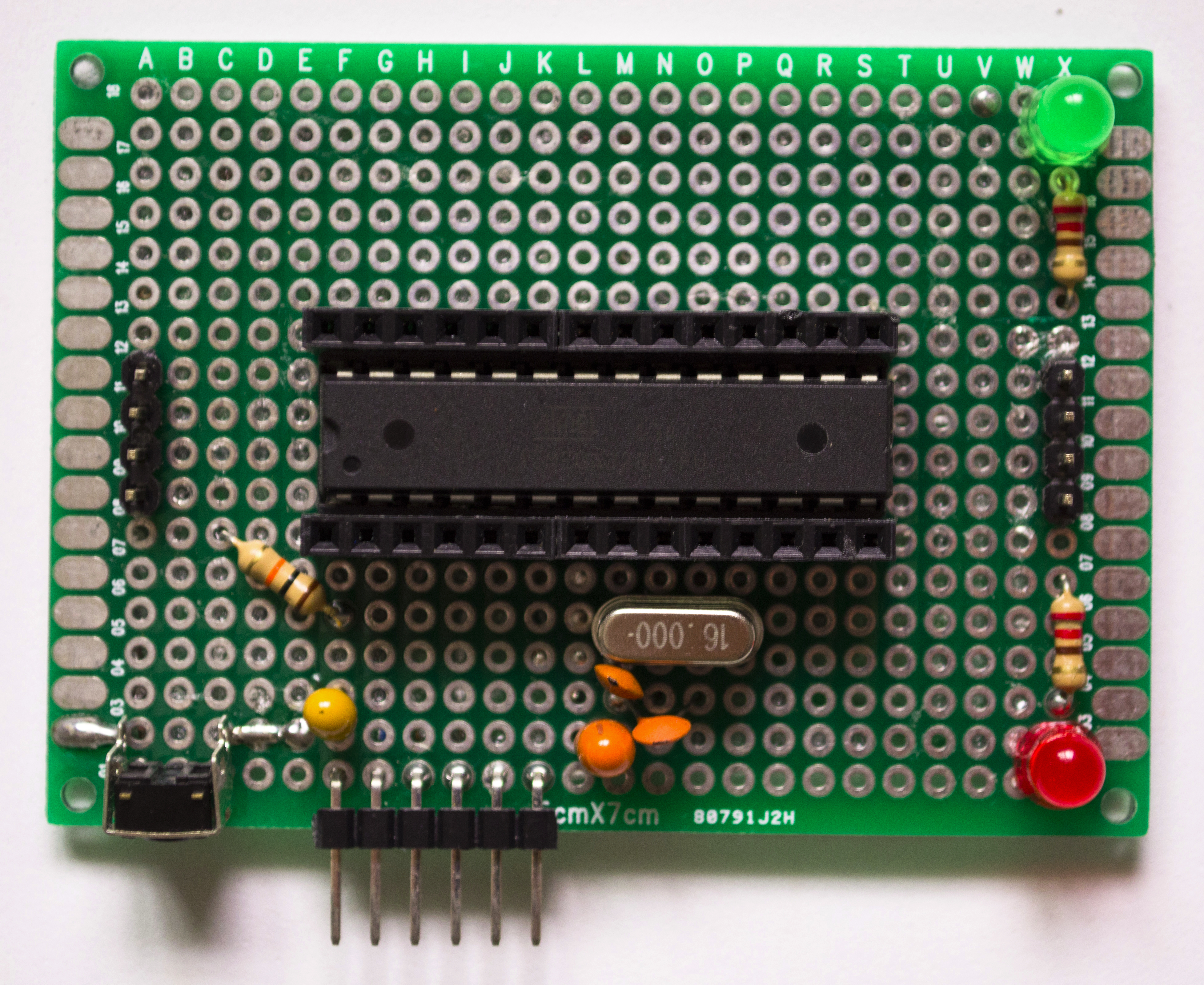
I used one of my DIY PIC18F4550 Pinguinos for experimentation. As you might guess, I decided to try the standard “Hello World!” program (i.e. blinking an LED). I wanted to create example PIC18F4550 assembler programs to blink an LED at intervals with a delay routine and with an interrupt timer. Also, I wanted both of them to work stand alone and with the Pinguino bootloader. You might also guess,  and be correct, that the internet is full of tutorials and code on how to blink an LED. Even the Pinguino WIKI shows 6 ways to blink an LED here, however all examples there are in ‘C’.

I did not find much on what I specifically wanted, especially using interrupts with the Pinguino bootloader. However, I did some experimentation and found solutions to make it all work.

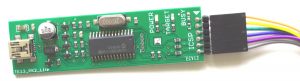
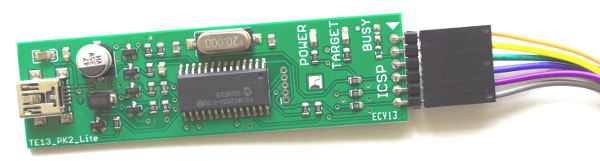
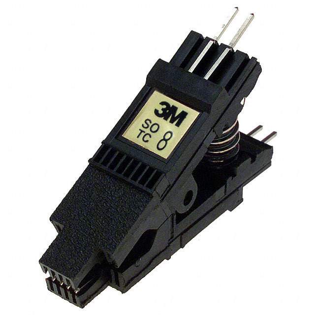
Before I show the code, let’s first talk about the tools I am using (under Linux). To assemble the source code, I use GPASM which is part of the GPUTILS package. You can download it here.  I am using a PICKit2 programmer clone from tepuyelectronics.com to burn stand alone programs and the Pinguino bootloader. It looks like this:

PICKit2 Clone Programmer PIC Assembler CodingI use the Microchip pk2cmd software to run it. It can be downloaded from here.This is a command line example to run pk2cmd and load the Pinguino bootloader:

Once the bootloader is burned in, ‘C’ programs can be compiled and uploaded via the Pinguino IDE. The output from the GPASM (PIC assembler) produces a hex format file which can be uploaded (to the bootloader) via the ‘stand alone’ uploader8.py Python script. For example:

The Pinguino bootloader(s) for various chips and clock speeds can be downloaded from here. That file also includes the uploader8.py script used to upload hex files to the bootloader.  Those same hex format files can of course be burned in stand alone (no bootloader) using pk2cmd.

Probably the best development tool for PIC microcontrollers is the Microchip MPLAB IDE which you can download from here. You can use it to develop ‘C’ and assembler programs.

Here is an example ‘C’ program for the PIC18F4550 to blink an LED used in an MPLAB IDE project:

Here is basically that same program in assembler (use GPASM to assemble it):

Here is basically the same assembler program but this time it is set up to be loaded into a Pinguino with a bootloader. (Notice the org 0x0c00 statement to locate the code beyond the bootloader.) It is a bit different as it uses TIMER0 in 16 bit mode.

The included file pic18f4550.inc is a standard header file which comes with GPASM. The included config1.inc is something I coded which sets up the CONFIG directives. Here is what it contains:

If you don’t set up the PIC fuse (configuration) settings correctly (especially for the clock speed) the timing will not work correctly.

Here is the stand alone assembler program to blink an LED using a delay routine:

To run that same program in a Pinguino with a bootloader, change the org 0x0000 to org 0x0C00 so it loads beyond the bootloader.  I used a script (found here) to generate the delay routine. Note: You may need to change the code it generates for the specific processor being used. I had to change the relative offsets it generated (the $+ statements) to match the  lengths of opcodes for the PIC18F4550.

The delay routine is interesting to look at for the sake of learning the code involved, however, the interrupt version is ultimately more practical.

If you are interested in PIC assembler coding there are only a few instructions to learn. View the documentation here. Also of interest would be the assembler user guide here.

DIY Arduino Shield

An Arduino shield is basically another circuit board that plugs into the Arduino and extends its capabilities in some way. So, of course, if you create your own DIY Arduino, you have to create a DIY Arduino shield.

I needed a way to attach an HD44780 LCD to my DIY Arduino so I created a shield for it. Here is how my DIY Arduino shield turned out:

DIY Arduino ShieldAnd here are pictures of the front and back:

DIY LCD Shield Front ViewDIY LCD Shield Back View


It has a 16 pin female header to plug in the LCD, a 10K potentiometer to adjust the contrast and a jumper to turn on the backlight. The backlight can also be turned on (if the jumper is off) by pin 10 which is connected to a transistor.

The shield itself is basically a 5×7 cm fiberglass board with two rows of 14 pin male headers. The 14 pin male headers plug into the female headers on the DIY Arduino and thus extend all the Atmega 328 pins onto the shield. This then provides an whole new surface area to work with. That is how a shield works as a means to enhance the functionality of the base Arduino,

The wiring for this shield is nothing special (it is the standard way to hook up an LCD). Here is a Fritzing graphic diagram:

LCD Fritzing Hookup Diagram

You can get the Fritzing diagram source file HERE. When the DIY LCD shield is attached and running, this is what it looks like:


DIY LCD Shield Connected

Updated DIY Arduino Uno

I have a new version of my DIY Arduino UNO. It is somewhat different than the old one that I have written about before (HERE).  I moved some components around on the board, added the user LED and moved all the wiring to the bottom of the board.

Here is a picture of what it looks like:

DIY Arduino [Top View]

Updated DIY Arduino Uno

If you’ve followed along in my blog posts, you will have seen other pictures of it in use.  Additionally, I have added an optional 40 (10 x 4) pin breadboard which makes it quite handy to test any add on circuitry. I also added jumpers to connect / disconnect the LEDs (to conserver power). I printed ‘stickers’ for the Atmega328 and used silicon to stick them on. Get them here.  The sticker makes it easy to tell which pin is which.

Here are pictures of the top and bottom views of one:


DIY Arduino [Top View]DIY Arduino [Bottom View]


The bottom view was taken before all the wires (necessary to complete the connections)  were soldered on. This updated DIY Arduino UNO features:

The parts list for my updated DIY Arduino UNO is very basic:

Even though the layout has changed, how things are connected has remained the same. View the larger graphic by clicking the image below which shows the basic connections. (Get the fritzing source .fzz HERE)

Arduino on a Breadboard

Experimenting with Arduino-Builder

Lately, I have been experimenting with Arduino-Builder. It was been available as a command line interface to compile sketches since version 1.6.6 of the Arduino IDE.  It is actually what the Arduino IDE invokes behind the scenes to compile the sketch.

It is written in the Go language. The source code is available HERE on github.com.

Arduino-Builder is easily invoked to compile all of your sketches with a script like this:

To see a list of all the ways it can be customized, invoke it without any parameters.

I am not a fan of the Arduino IDE due to lack of an easy to use editor.  I’d prefer to use VI to edit Arduino sketches. However, the IDE does have an easy way to compile the sketches and load them via AVRDUDE.

Arduino IDE


Now that I’ve been experimenting with Arduino-Builder, I came up with a bash script to both compile and load a sketch.

The bash script:

Experimenting with Arduino-BuilderNow, I have the best of all worlds (so to speak). I can edit a sketch using VI and run the script containing Arduino-Builder to compile and load it.

An ATmega328 with two Identities

Some would say that an ATmega328 with two identities is not possible. However, it depends on who you ask.  🙄   First though, before we ask, here is some necessary background information.

Microcontrollers from Atmel (AVR) and Microchip (PIC) have a built in ‘signature’ or identity. This signature is a unique code that identifies its model. When you program a chip (for example, upload a sketch in the Arduino IDE),  the process checks that the chip selected matches the type it’s connected to. This protects the microcontroller from user error. Therefore, a chip has only one built in identity, that is, if you ask it. However, sometimes, a program it runs speaks for it and tells a different story. So an ATmega328 with two identities is possible. Let’s find out how.

While making a new batch of my DIY Arduino UNOs I bought some ATmega328 microcontroller chips. An original Arduino UNO has an ATmega328P microcontroller. The P designation means picopower. There are ‘minor’ differences between the ATmega328 and ATmega328P but for my purposes the ATmega328 works essentially the same as the P version. Even though they function the same, they have different signatures. Since the ATmega328 is not used in an Arduino, that chip is not recognized/used by the Arduino IDE unless we make some changes.

Let’s take an example of how the Arduino IDE burns the bootloader for an ATmega328(P).  Here is how things are physically connected:

An ATmega328 with two IdentitiesGet the fritzing diagram HERE.

Behind the scenes, the Arduino IDE uses the AVRDUDE software to do the programmimg (uploading the sketch). AVRDUDE ‘talks’ to various hardware (and software) programmers which physically connect it to the microcontroller chip. The Arduino IDE runs AVRDUDE in the background with specific parameters on how it should run.  We are specifically interested in three parameters (-C -c -p). I will leave it up to the reader to consult the AVRDUDE documentation if they are interested in the other parameters.

The -C parameter specifies the file with various microcontrollers AVRDUDE can program and their respective identities. (By the way,  this configuration file does specify and recognize both the ATmega328 and ATmega328P.) The -p parameter specifies the part (i.e. the chip) being programmed. The -c parameter specifies the ‘hardware’ programmer being used. That ‘hardware’ programmer could also be emulated in software.

The specific parts of the AVRDUDE command which the Arduino IDE creates to burn the bootloader is similar to the following:

Notice that the part is the ATmega328p and the programmer is the stk500v1. It is not in reality an stk500v1 piece of hardware but in our case it is being emulated in the sketch called ArduinoISP. Looking at the above hardware diagram, notice that the device we are using to program the chip is an Arduino UNO to which we must first upload that ArduinoISP sketch for it to act as an stk500v1. Now comes the identity problem. When we try this command when the physical chip is an ATmega328 and the -p is an ATmega328P we will get the following error:

This is because the sketch (emulating the stk500v1) talks directly to the chip and gets its identity (0x1e9514) which does not match the identity (0x1e950f) which AVRDUDE has in its configuration file. There are several ways to get around this problem.

  1. Copy the command generated by the Arduino IDE and manually run it after changing the -p to atmega328 (instead of atmega328p)
  2.  Edit the AVRDUDE configuration file and change the signature of the atmega328p to match that of the atmega328

Personally, I do not like either of these, specifically due to all the manual effort involved. A better solution is to use a sketch called ArduinoISP_Multi (which is an updated version of the ArduinoISP sketch). You can get the Arduino_Multi sketch HERE. The ArduinoISP_Multi sketch will tell AVRDUDE that the chip identity is 0x1E950F for both the ATmega328P and ATmega328.  Remember that the identity matching is there to protect from putting code into the wrong chip. Since the ATmega328 and ATmega328P are essentially the same, the identity can be ignored for our purposes in this case. So now the bootloader can be burned in and all is well.

Wait a minute you say? If the Arduino IDE only uses the part (-p atmega328p) what happens when you upload a sketch to that new ATmega328 that has the new bootloader. Won’t it give the signature error?

Here is where the two identities come into play. Notice the command that the Arduino IDE builds to upload a sketch:

The part (-p) is ATmega328p but the programmer is different. The -c parameter is arduino (not stk500v1). In this case the programmer that AVRDUDE is talking to is the bootloader. The bootloader was designed to return an identity of 0x1E950F (the ATmega328P) which it does even if it is running on an ATmega328.

So, you can have an ATmega328 with two Identities. The real identity of the chip internally and its ‘fake’ identity returned by its bootloader. Once the bootloader is there, when you load sketches via the Arduino IDE, it thinks its talking to a real ATmega328p even though physically it is an ATmega328.

So in the end, the identity of the chip all depends on who you are talking too. 🙄

If you have the time

The arduino does not have an RTC (Real Time Clock). However, it is trivial to add one.  And if you have the time, you can do a number of interesting things with your arduino, limited only by your imagination.

I am using the DS1307 RTC module which looks  like this:

If you have the timeRTC DS1307 Back View


It uses a CR2032 3V Lithium coin battery to keep the date and time when there is no power source. It is connected to an arduino via 5V, GND, SCL and SDA pins.

Here is the Fritzing diagram which shows how to wire it up:

RTC Module Fritzing DiagramNote: This diagram shows the DS1307 module from Sparkfun.com, however the pin wiring is the same (5V, GND, SCL and SDA) for the module I have. You can download the fritzing source HERE.

When this module is first put into use, the date and time needs set. Rather than write your own code to control the DS1307, it is easier to use an existing library. I am using the RTC library from Adafruit. You can download it HERE.

The sample sketches in the RTC libraries usually have a means of initially setting the clock to a specific date and time. And usually it is set to the date and time of the computer which loads its sketches. It is wise to first make sure that computer is synced via NTP to an NTP server.

Also, that time setting code is initially commented out. You need to uncomment (or change) that code to set the specific time desired then upload the sketch.  Once the date and time is set you must remember to uncomment the code and upload the sketch a 2nd time.  Otherwise, if the original sketch is run each time you run your arduino, the time is reset to the time set in the sketch (not the current time).  For example, this line of code:

rtc.adjust(DateTime(F(__DATE__), F(__TIME__)));

gets the date and time from the computer the sketch is compiled on which becomes a hard coded value in the sketch. These values (__DATE__ and __TIME__) are inserted at compile time and not when the sketch is running.  Since it takes a few seconds to compile this code, burn it into the arduino and verify it.. the time will already not exactly match the real exact time. Also, since most of these sketches display the time on the serial console, they are prefaced with this line:

while (!Serial); // for Leonardo/Micro/Zero

which means that if you don’t start  the serial console right away the time is going to be off further.  My solution to these problems is to have a simple sketch that just sets the time and nothing else,  like this:

Then load the sketch from your imagination that uses the RTC.

Connecting an Android Phone to an Arduino

Connecting an Android Phone to an Arduino could not be easier. All you need is an OTG cable. I wrote a previous post here about connecting and controlling an Arduino from your Android device. Previously, I had always connected real Arduinos. This time I tried connecting my DIY Arduino.


Connecting an Android Phone to an ArduinoConnecting an Android Phone to an Arduino


Pictured above is my Samsung S5 (G900H) connected to my DIY Arduino via an FTDI converter and a white OTG cable. The FTDI converter would normally be plugged into your Host PC USB port. With the OTG cable, the Android Phone functions as the host. From the screen shot of the phone, you can tell that the Arduino is loaded with the Minipirate sketch. The phone is running the USB Terminal app. Note: some Android phones do not support USB host mode. To check if yours does, I recommend this app.

When I first connected my Arduino to the Phone it did not recognize the connection. I found out that my FTDI chip had an incorrect product id. The product id was all zeros and needed to be 6001. There is a solution to fix this called ft232r_prog. This Linux command line program allows you to reconfigure (i.e. flash) the FTDI chip. It is a few years old and does not compile on my version of Fedora. (At the time of this post, I am using Fedora 24.) It does however compile fine on an Ubuntu distro. I used YUMI to boot into a live Ubuntu image to compile and run it. Here are the commands to install the prerequisites, compile and change the product ID on an Ubuntu system:

After changing the product id,  the USB terminal app connected to the FTDI converter fine.

Connecting an Android Phone to an Arduino allows you portability in the field. You will want a means of re-charging or replacing the phone battery as the Arduino connection does drain the battery faster than normal.

Flashrom and an Arduino at 3.3V

Flashrom is an amazing piece of software and a life-saver when you need it! If you’ve tried to update your BIOS before using manufacturer supplied software and something went wrong, then you know how valuable Flashrom can be. I’ve written about Flashrom and the BusPirate in a previous post HERE. However, I just found out how easy it is to use Flashrom and an Arduino at 3.3V to program (read, write and erase) various ‘flash’ chips.  All Flashrom needs is a programmer to interface with. The Arduino (or Atmega 328P) can very easily and economically be made into a Flashrom programmer.

Basically a program is loaded into the Arduino to let Flashrom program through it. I am using frser-duino which Flashrom sees as a ‘serprog’ programmer. Serprog uses the FTDI chip, the serial port and SPI interfaces to do its work. More information about Flashrom using the Serprog ‘programmer’ can be found HERE. You can get the source code for frser-duino HERE.

I am using Fedora (24 as of the date of this post). Here are the commands I used to install the prerequisites and the frser-duino code into my Arduino (a DIY UNO).

Notice that the documented commands are not what I used as they are for a ‘real’ Arduino UNO. Since I am using an external FTDI chip, it needs to specify 115200 BAUD to program the Arduino. However, once programmed, the larger BAUD/buffer rate of 2000000 can be used to flash with. Once the code is loaded via avrdude into the Arduino, you are ready to use it with Flashrom.

One of the ‘problems’ in flashing BIOS chips is that they are usually 3.3V whereas the Arduino is usually 5V. You could use level translation circuitry to reduce the voltage but it turns out there is a much simpler way. The DIY Arduino can be run at 3.3V using an FTDI USB to Serial converter. A DIY version of an Arduino UNO can be easily made on a breadboard, PCB or perfboard.

Here is an example of how an 8-pin Winbond BIOS chip is wired to the Arduino (download the Fritzing source HERE):


Flashrom and an Arduino at 3.3V


DIY ArduinoHere is a picture of my newest DIY Arduino. It is a bit different than other Arduinos I made in the past and wrote about HERE. You can see the 6 pin ICSP header on the side (to attach the FTDI USB to serial convertor). Two 14 pin female headers are soldered to the base for connectivity to any pin. There is a 4 pin header for power (left side) and a four pin header for ground (right side). This is basically a bare minimum circuit to run the ATMega 328P and function as an Arduino UNO. It runs at either 5V or 3.3V depending on the jumper of the FTDI USB to serial convertor.


6 pin dual female cableA 6 pin female-female cable is used to connect the FTDI converter to the 6 pin male ICSP header on the Arduino. The six pins are GND,CTS,PWR,TX,RX,DTR.


FTDI - USB Mini ConverterFTDI USB-Serial Convertor


The FTDI USB to Serial Converter I use has a jumper to switch between 3.3V and 5V. I got mine from HERE.Sparkfun.com also sells one HERE. I have the jumper on 5V when I load the Arduino with the frser-duino code. Then I switch the jumper to 3.3V when I use Flashrom to program chips that need 3.3V.

Here is a picture of everything wired together:

Arduino Flashrom Programmer

Flashrom and an Arduino at 3.3V

If the BIOS chip is not soldered on, it can be extracted and placed on a breadboard to flash. However, if the BIOS chip is not socketed (i.e. it is soldered on), you may need an SOIC Test Clip or IC Test Hooks.


SOIC 8-pin Test ClipIC Test Hooks


Sometimes it is hard to use the SOIC test clip due to other circuitry in the way so I prefer the IC Test Hooks. They have a tiny ‘claw’ which can be clamped onto the leg of the IC.
IC Test Hook Claw


Here is an example command to run Flashrom and save the contents of a BIOS chip to a file:

Here is an exmaple command to just identify the flash chip:

here are the results:

As a side note, the BIOS file to flash has to be in the proper format (ROM image). ASUS for example, distributes their BIOS files in CAP format.  The ROM image has to be extracted from the CAP file with a utility like UEFITool. Alternatively, and much easier, just strip the header off the CAP file with this Linux shell script:

TV Video Output from the Arduino

I made another circuit to display TV Video output from the Arduino.

It uses the TVOut library (documented at the TVOut Arduino Playground) which can be used to output an NTSC or PAL video signal. The circuit is actually just a means of adding three resistors to an RCA video cable. Instead of cutting a cable and soldering on the resistors, it is much cleaner to use this circuit. The circuit is very simple, consisting of an RCA jack, three resistors and a three pin PCB connector. Normally, only two resistors are used (a 1K ohm resistor to sync and a 470 ohm to video), however, some TV/video monitors need an additional 75 ohm resistor from video to ground. Therefore, I also added that 75 ohm resistor in my circuit. Here is a picture of the circuit and the Fritzing diagram showing how to hook it up to an Arduino Leonardo:


TVOut RCA Jack Circuit Top ViewTVOut Fritzing Graphic


If you want diagrams’ Fritzing source file, download it from here.

I tried the TV Video output from the Arduino at first with my Arduino of choice, a Leonardo, and found that it did not work when the Leonardo is powered from a USB cable attached to a PC. The screen flickered too much. When the Leonardo was powered from a wall plug or battery, it functioned perfectly. I found that other Arduinos (the Uno or Mega) work fine from a PC USB power connection. Depending on which arduino you use, you will need to adjust where the video and sync pins are connected. There is a handy chart on the TVOut Arduino Playground documenting the pins used for various arduinos.

For small projects and portability, an LCD is great to use to display output from an Arduino. However, if your next project needs to display data from an arduino so more people can see it (perhaps a large screen TV), you might consider using the TVOut library and this simple circuit.

The TVOut library has a sample NTSC demo sketch. Here are two of the captured TV screens it outputs:


TV Video Output from the Arduino TV Video Output from the Arduino

Load more