WebRTC Screen/Video Sharing

As many readers of this site can tell, I am a bit off topic with this article. None the less, I think those same readers will find it useful. The topic is WebRTC Screen/Video Sharing and shows how to communicate with another person (peer to peer) via video and audio using a Web browser.  This can be very useful to share a ‘screen’ or video and provide remote assistance / technical support.  Complete code and documentation is also provided to try it out (or view the documentation to see the features and if they are of interest).

As working from home becomes more prevalent these days, there is a greater need for this type of service. There are popular software products which offer some of these services, however,  perhaps you are like me and want to try/code these things yourself.  I get the features I want and I control  the (sometimes overlooked) security aspects of the service.

For those not acquainted with WebRTC, it is a means of communications between two peers. (RTC is an abbreviation for Real Time Communications) WebRTC allows for secure sharing of audio and video directly between those two peers, browser to browser (usually without anything in between).

For example, If someone has a problem/question on their computer (perhaps about the Arduino IDE) and you want to show them how something is done, get on the WebRTC Screen/Video sharing page with them. Then share  a screen and ‘walk’ them through the process in question.

WebRTC uses an API built into most modern day browsers.  Technically there are several protocols involved in WebRTC (signalling, ICE, STUN and/or TURN). For more specific information on WebRTC, see the WebRTC.org site.

Specifically, the Web application that I am showing in this article, uses the WebRTC API to allow two users to securely communicate via audio/video over a peer to peer connection in real time.  Each of the two ‘peers’ using this Web app would need to have a video device (Web camera), microphone and speakers or headphones.

Features for this Web app include audio, video and/or screen sharing, screen capture, video capture/replay/download, chat messages, file transfer and playing a local video to stream it to the remote peer.

Technically I am not using a ‘Web’ server (like Apache or Nginx) to serve the Web page. I have coded a Node.js server script (in Javascript) which functions as a Web server in that it handles the browser HTTPS Web page request and serves back the Web page.

Here is the code for  the Node Server:

Note: The script (and WebRTC) requires an SSL certificate to ensure secure communications. Make sure to replace the lines (with key: and cert: with valid certificate references). Note: The port serving the Web page is 8080 which can be changed to any port (not conflicting with other ports in use on the server).

The modules required for the node server can be installed via npm:

npm i ws fs  https

To start the node server, use the command:

node server.js

To access the WebRTC app, in addition to the node server, a STUN and/or TURN server is also required.  For the peers to communicate, they need to know how to contact each other and therefor need to know each others’ IP address.  The STUN or (TURN) server provides this info.  The TURN server is needed if one or both of the peers is behind a NAT. As mentioned earlier, for more specifics on how WebRTC works check the the  documentation on the  WebRTC.org site. There are public STUN servers available so no need to run your own.

However, if a TURN server is need, the coturn open source TURN server is the one I recommend.

The main functioning of this app is via the webrtc.js javascript code. There are two lines  in the webrtc.js script which must be edited and changed to replace the urls for the STUN/TURN server references.

Also, if the port is changed in server.js, make sure to change it in the webrtc.js source to match also.  Once the node server is running and the changes are made to the webrtc.js script for the STUN/TURN server references, the WebRTC app is ready to go.

Using the Firefox or Chrome browser, navigate to its page:

https://yourdomain.com:8080/webrtcvideo

Replacing  yourdomain.com (and optionally the port) with the actual domain name running the node server script.

The browser will ask if it is OK to share your video and audio device, once approved, the Web Page will show up:

WebRTC Screen/Video Sharing


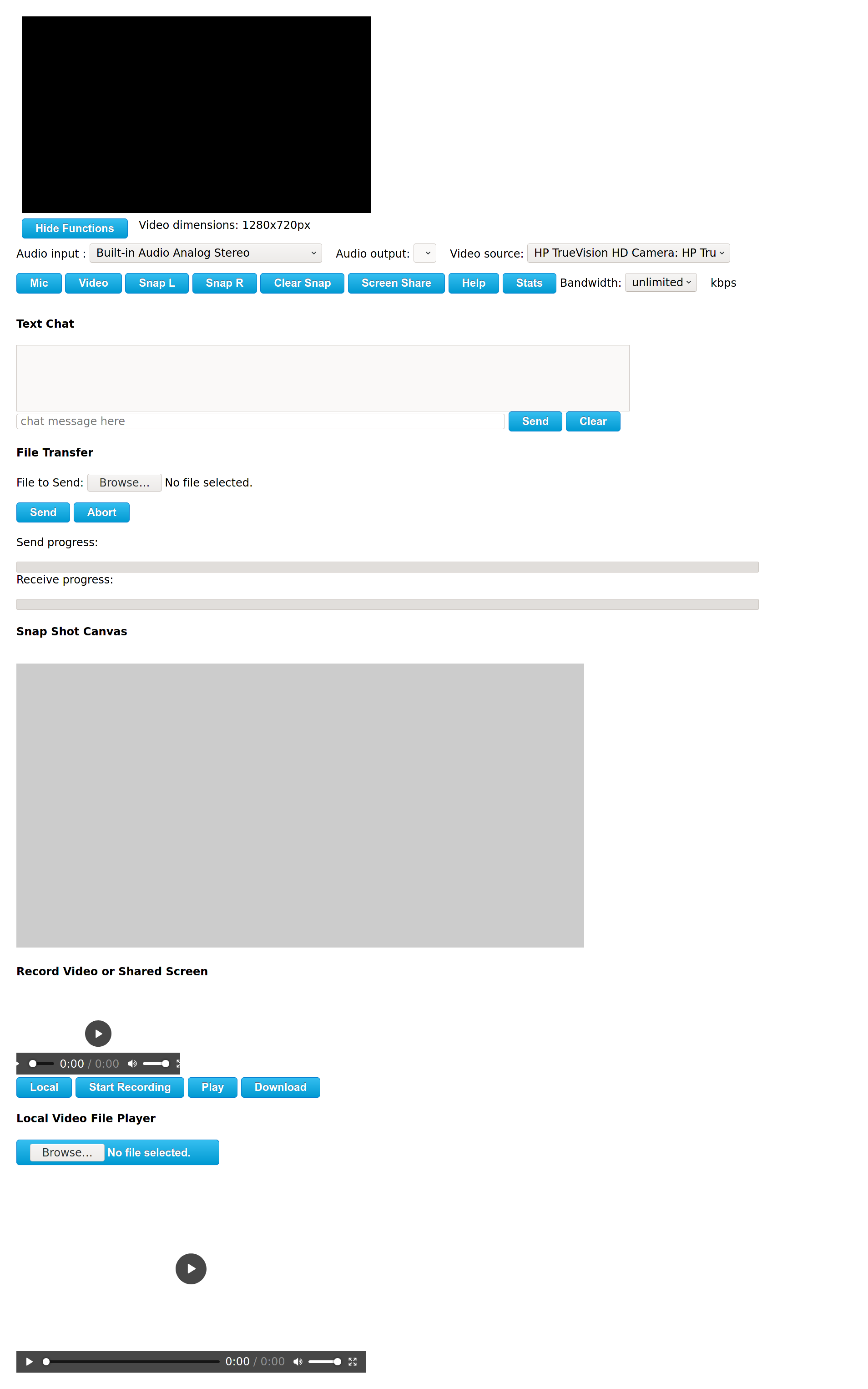
Click the ‘Show Functions’ / ‘Hide Functions’  button to show or hide all of the extra features available for this app. View or download the documentation (HERE) for an explanation of the features.

The complete source code ( a ZIP file which includes the documentation) , can be downloaded (HERE).

A Wireless WEB Server on an ESP8266

This is a short post which shows how to create a wireless WEB server on an ESP8266.  It uses a microcontroller, in this case an STM32F103C8T6 (BluePill )  to send commands and control the ESP8266

Here is what the wiring looks like:.

A Wireless WEB Server on an ESP8266


You can get the Fritzing code for this image here.


Here is the Arduino IDE source code to load into the STM32F103C8T6 (BluePill) to create a Wireless WEB Server on an ESP8266:

If you open the serial monitor on the Arduino IDE while the code is running you will see the commands being sent to the ESP8266 and its response. You can also watch what comes to its WEB site and what it sends out in return. This can be an interesting learning experience for the beginner.

This is a simple project to make but can be the start of a bigger project or added to another circuit to add wireless capabilities.

STM32F103C8T6 Solar Power System Monitoring

If you read my last post on Solar Power System  Monitoring with an Arduino you might be wondering if that circuit could be enhanced a bit. Say, change the LCD to an OLED and add wireless (WEB server) capability?

I was not happy to have to go out and look at the device when I wanted to see the info. So I did enhance it a bit. I changed the LCD to an OLED for more info in case I did happen to be where the device is and I added a wireless module (an ESP8266). The wireless module has a WEB server so I can just connect wireless via a browser and see the info.

Since the ESP8266 needs 3 Volts, I also changed the ‘arduino’ I was using. I switched to an STM32F103C8T6 (BluePill) since it can take 5 Volts and output 3 Volts.  This new circuit still uses the LM7805 voltage regulator to take the 14 Volt input and then output 5 Volts. It also keeps the SN75176BP for the RS485 protocol conversion.  If you have not read the previous post, you can find more details there on those components.

Here is what the circuit wiring looks like:

STM32F103C8T6 Solar Power System Monitoring


You can get the Fritzing code for this circuit here.


Here is what the circuit looks like (top and front side view):

STM32F103C8T6 Solar Power System MonitoringSTM32F103C8T6 Solar Power System Monitoring


The left side has the STM32F103C8T6 and the RJ11 connector. The right side has the ESP8266, the OLED, the SN75176BP and the LM7805. The LM7805 has a heat sink on it since it gets a bit hot. The STM32F103C8T6, ESP8266, OLED and  SN75176BP are all in sockets for easy (re)placement. This circuit has all the ‘messy’ wiring and soldering on the bottom (hidden from view).  In my previous post I still had all the components on a breadboard.

Here is the code to load into the STM32F103C8T6 (using the Arduino IDE):

I am using the Adafruit GFX and SSD1306  libraries to control the OLED. The ESP8266 is just connected via a serial connection and sent commands to set it up as an access point and WEB server.

The wireless access point name is just set to ESP8266. You can change it to anything you want. The IP address is 192.168.4.1, so just go to that IP address in a browser after connecting wirelessly. The WEB page will refresh every 5 seconds.

My next step is to enhance the code to display more info as it still only outputs the codes like the LCD version does. Here is a picture (photography is not my forte) of the device on top of one of my Lithium Batteries (from Deeds Solar Solutions).


Solar Power System Monitoring with an Arduino

Sometimes, people wonder about the practical side of using an arduino. I do get asked what is the real use for some of the articles I post here.  Are these ‘gadgets‘ just toys or do they have a practical use?  Most people who ask though, are not that familiar with arduinos or microcontrollers in general.

So, this post is a partial answer to some of those questions and a place I can refer people to.  Although, if people were really curious, a search would show them a number of practical uses for arduinos and microcontrollers in general.

For example, I recently posted articles on using an arduino to communicate via the RS485 protocol here and here. Another post shows how to use an LCD (using only 3 pins) with an arduino here.

This post will show how to use the knowledge gained from those posts (plus a bit more) to build an arduino ‘gadget’ which can be used to monitor an inverter. Hence, the title of this post:  “Solar Power System Monitoring with an Arduino”.

An inverter is an essential part of a solar power system which uses sun light (solar energy) to produce electricity.

A solar power system (initial investment) can be quite expensive, depending on energy needs. Replacing parts is also expensive.  Monitoring what is happening with the solar energy conversion to electricity and its subsequent usage, is a very important part of the system to make sure it is being used efficiently and properly. If we can use an arduino for monitoring (which we can), we thus have a practical use for it (especially considering the price of buying commercial products versus do it yourself with an arduino).

I happen to have a Magnum inverter which is connected (and controlled) by an ME-ARC remote monitor. I was wondering if the ME-ARC is really needed and if it could be replaced with an arduino and an LCD screen. In my testing, I found out that the ME-ARC is not needed to actually run the inverter and it can be replaced with an arduino. What follows documents how it can be done.

The only connection into the ME-ARC is an RJ11 cable from the inverter. This RJ11 cable is the same type of cable used to connect telephones to wall jacks.

Since there is no external power cable, the RJ11 connection must be supplying both power (volts/ground) and data.  Further information is needed on how the remote gets power and data from the inverter. This information is in the Magnum Network Communications Protocol document found via a search.

From the document, we can see that the RJ11 cable does indeed provide power (14 Volts, Ground) and data. The protocol in use for data interchange is RS485. So we can use the information from my earlier posts to see how we can attach an arduino to the inverter. Note: The end of the document has a ‘Third Party Notes’ section which concerns  connecting your own device to the Magnum Network. How did they know we were going to connect an arduino ?  🙂

The RJ11 (4 wire) connection is wired like this:

Looking at the ‘front’ of the RJ11 connector (where it plugs in)  with the tab  at the top and wires going away to the back,  pin 1 is on the right side,  pin 4 is on the left side.

Since the arduino and the LCD need 5 volts to work and the inverter is sending 14 volts, we need a way to regulate the 14 volts down to 5 volts.

Here is the simple circuit to accomplish that.

LM7805 Voltage Regulator


Get the Fritzing code for that circuit image here.


LM7805 Circuit

This is what the circuit looks like when built.


I used an RJ11 splitter to attach both the ME-ARC and my arduino at the same time.

The splitter RJ11 Splitterwas connected to the back of the ME-ARC. The RJ11 cable from the inverter was plugged into one side of the splitter and the cable to the arduino was plugged into the other side of the splitter. Wiring that way allows viewing the ME-ARC and checking what it is showing versus what the arduino is showing. This is a good way to check that the code in the arduino is providing the same (accurate) results.

Since the communications from the inverter uses the RS485 protocol, we will use the wiring shown in a previous post which uses the SN75176BP IC for the protocol conversion.

If you haven’t taken the time to read that post, here are the wiring diagrams for the SN75176BP (left) and the complete circuit (below). The diagram shows RS485 communications between two arduinos, however, we can just pretend that one of the arduinos is the inverter. In fact, one of the arduinos was running code to emulate the inverter for testing purposes but I did not mention that in the original post.  Now you know. 🙂

SN75176BP RS485 Communications using Arduinos

Get the Fritzing code for that diagram here.  For connecting just one arduino to the actual inverter, the ‘A’ pin (from the RJ11 connector pin 4) connects to the ‘A’ pin of the SN75176BP and the ‘B’ pin (from the RJ11 connector pin 1) connects to the ‘B’ pin of the SN75176BP.

LCD Shift Register Circuit for an LCD


In hooking up the LCD to the arduino, we will also use the information from a previous post.  There we show how to use a shift register IC to minimize the number of pins used to connect the LCD to the arduino.


Now that we have all of the hardware details, we can hook it all up. The RJ11 splitter is connected to the ME-ARC. The RJ11 cable from the inverter is connected to one side of the splitter. The other side of the splitter is connected to the arduino circuit this way:

Here is what it looks like all attached and working:

Solar Power System Monitoring with an Arduino

From the picture, you can see the RJ11 cable (on the right) dropped down from the splitter on the ME-ARC. I have an RJ11 female/female connector to the cable and to an RJ11 connector which breaks out the 4 wires connecting to the arduino and the voltage regulator circuits.

You are probably wondering about the output on the LCD? Since the LCD has only 16 characters x 2 lines, it has limited space to display things. The first line has ‘codes’ for what it is displaying:

The 2nd line displays the DC volts and  amps being used just like the ‘Meter’ on the ME-ARC. The code in the arduino gets these values from a data packet sent by the inverter every 100 milliseconds. The Magnum Network Communications Protocol document (mentioned earlier) details the communications and values being sent.

Here is the arduino code so you can see how the arduino captures the inverter data, waits for the 100 millisecond ‘gap’ and then decodes and displays the values.

One serial port is used for communications to the inverter and another is used to optionally communicate with a PC and get commands to send to the inverter. Note: The code for transmitting data to the inverter is there but commented out.  I am using the Software Serial library (to emulate an additional serial port) because the Arduino Nano I am using for this project only has one serial port. The other library (LiquidCrystal595) is needed to control the LCD with only 3 pins. Make sure, if you use that library, to patch it according to the comments in my post about it mentioned above and referenced again here.

Since the inverter sends a data packet every 100 milliseconds, we can check for that ‘gap’ (no data being sent) and know that we have a complete packet.  However,  since it will take some time to run the code to display on the LCD we need to pick a ‘safe’ value for checking that timing. You will notice in the code:

the timer holds the number of milliseconds since the last input byte from the inverter. I chose a ‘safe’ value of 30 (milliseconds) which should give enough time to display on the LCD and get back to checking for inverter data.

The next step would be to test sending data to the inverter as does the actual ME-ARC remote. Only then would we have something to be able to totally replace the ME-ARC.

So now you can see that there are ‘building blocks’ (so to speak) in my posts which used together can produce something practical, Solar Power System Monitoring with an Arduino.

How a Web Server on an STM32F103C8T6 can be used to control a Relay Switch

Here is the circuit showing how a Web Server on an STM32F103C8T6 can be used to control a Relay Switch:

BluePill As A Web Server With A Relay SwitchThe Fritzing code used to create that diagram/image can be downloaded here.

An ENC28J60 ethernet module is used to connect the STM32F103C8T6 (BluePill) to a network.

Here is the source code for the sketch to load into the STM32F103C8T6 (BluePill):

This is an updated and enhanced sketch from a previous post on a WEB server using both the BluePill (STM32F103C8T6) and the ENC28J60 module. It seems the UIPEthernet  library has changed since then. I had to add these lines to the code to define the correct pin settings:

The source code has the IP address and network settings for the ENC28J60 ethernet module hard coded. Those settings may need changed for use on a different network.

The relay switch can be attached to any number of AC type low current devices and turned ON/OFF by accessing the WEB server. (The relay switch can possibly handle low current DC devices as well). I used a 2N3904 NPN transistor in my circuit to allow the STM32F103CT6 to turn the relay OFF and ON. This circuit also has a red LED to visually show when the relay is ON or OFF.

The WEB server accepts several ‘commands’:

http://192.168.0.150/led

http://192.168.0.150/analog

http://192.168.0.150/switch

‘LED’ toggles the internal LED On/Off, ‘analog’ displays the analog values of the first 4 analog pins and ‘switch’ toggles the relay On/Off.  So now you know how a Web Server on an STM32F103C8T6 can be used to control a Relay Switch.

SN75176 RS485 Communications between two Arduinos

Previously, I wrote about RS485 communications between two Arduinos using a MAX485 IC. The link for that post is HERE.  It showed one Arduino as a tranmitter and the other as a receiver. This post is very similar, however, I am using a different IC, the SN75176BP. This post is about SN75176 RS485 communications between two Arduinos which allows either one to transmit and receive at the same time.

The SN75176 IC is also an RS485 transceiver like the MAX485 however it is full duplex where as the MAX485 is only half duplex. Full duplex allows sending and receiving at the same time.

Here is the pin layout for the SN75176BP IC which I am using:

SN75176 RS485 Transceiver


This chart shows the function of each pin of the SN75176:

Using two Arduinos, each with an SN75176BP, we can establish two way communications:

SN75176 RS485 Communications between two Arduinos

SN75176 RS485 Communications between two Arduinos

The Fritzing diagram source is HERE in case you would like to modify it.  Note that the RE (Receiver Enable) pin is wired permanently low. The DE (Driver Enable) pin is turned on (high) only when data is sent.

The Arduino UNO that is used here only has one serial device, so the software serial library is used to add another serial device on pins 8 and 9. The software serial port is used to communicate (via RS232) to the SN75176 and the built in serial port (via USB) is used to communicate (via RS232) with the host computer the Arduino is attached to.

Load the following code into each  Arduino:

Attach a serial connection to each Arduino and data can be sent back and forth thru the  connection between the two SN75176 ICs.  Use my handy updated Python serial communications program for that purpose:

Once this is working, you have a ‘prototype’ to emulate other equipment or use ‘half’ (one Arduino and one SN75176) to attach to other devices using the RS485 interface such as Modbus RTU.

Use An Arduino Leonardo and a Button for a USB Foot Pedal

It is possible to use an Arduino Leonardo and a Button for a USB Foot Pedal.  Here is the story on how one was built.

A long time ago, my daughter used to transcribe audio cassette tapes using a transcribing machine. It had a nice foot pedal to start, stop and rewind the cassette tape. Recently, she decided to get back into transcribing. Instead of audio from cassette tapes, she is transcribing MP3 audio files on the computer. She choose a software program called ‘Express Scribe Transcription Software’ from NCH Software for that purpose. It allows her to use any sort of word processing software to key in the text transcription while she listens to the audio it plays. Express Scribe allows her to map keys, which it intercepts, to stop and restart playing the audio. A nice feature that it has, is that it automatically goes back several seconds when stopped so no ‘rewind’ is really needed.

Here is a screen shot of what that software looks like:

Express Scribe Transcription Software
The Express Scribe Software also works with several different USB foot pedals.  The USB foot pedal acts as an extra keyboard and sends keystrokes when the pedal is pressed. If you have ever done any transcribing, you will know how handy using your foot is, versus using the keyboard for stopping and starting the audio.

Rather than buying a USB foot pedal, Dad was asked if there was an Arduino solution. Dad of course took up the challenge.

The first step in the process was to set up a prototype of the process. An Arduino Leonardo was chosen (due to Dad having several around) and due to the Leonardo being able to plug into the computer and function as a USB keyboard.

Every USB device is assigned a device class, which defines what exactly its general purpose is. The Leonardo can  be programmed  to act  like a mouse, keyboard or other HID (Human Interface Device) class USB device, so it is just right for this project.

A simple circuit was constructed to test the functionality of the Leonardo sending keystrokes when a button is pressed.

Here is the circuit (just a basic button circuit):


You can get the Fritzing code used to create that diagram HERE.

The Express Scribe software was configured to use the ` key for stopping playback (and rewinding) and the Tab key was configured to start the playback. So the Arduino Leonardo sketch was coded to send those keys when a button was pressed.

Here is the sketch (i.e. the code which is compiled via the Arduino IDE and loaded into the Leonardo):

You will notice that only one button is used. There is not a separate button for stop and start. There is really no need. The sketch keeps track of what comes next. Pressing the button alternates between sending the Stop and Start keystrokes. Since the software takes care of the rewind (on stop) there is no need for that function via the button.

That code and the sample circuit was plugged into the PC via a USB cable to the Arduino Leonardo for testing and worked very well. The next step was to build something that could function as a foot pedal (i.e. allowing the foot to press the button).

An important consideration in this project is that whatever is used as a ‘button’ for the foot pedal be easy to push and still function as a ‘button’.   Here are some pictures of the large ‘gaming’  type buttons that works well for our purpose:


To use an Arduino Leonardo and a Button for a USB Foot Pedal we also needed something to house the Arduino and keep the button stable on the floor.  Here is where the brother (or son depending on who’s view you are looking from) comes into the picture.   The brother is adept at wood work so he was tasked with coming up with that.

RS485 Arduino Communications

There are various ways for two Arduinos to communicate information. A common way is serially via RS232. However, RS232 has distance limitations. If there is a need to serially communication over a longer distance consider using RS485 instead.  A couple of MAX485 ICs can facilitate RS485 Arduino communications over that longer distance.

Two MAX485 ICs connected together will take RS232 signals and perform the voltage level conversions required to turn them into RS485 signals and back again to RS232 signals. That will allow two Arduinos to communicate serially over a longer distance.

This chart shows the specific pin functions on the MAX485:

Here is how to connect the two Arduinos using two MAX485 ICs:

Max485 Arduino Communications

Get the Fritzing source HERE.  5V is used in this simple demonstration. For longer distances a higher voltage will be needed to power the MAX485. Also the BAUD rate will need to be adjusted (the longer the distance, the slower the speed).

This is the source code for the Transmitter:

This is the source code for the Receiver:

Here is what it looks like (messy wiring and all):

MAX485 ArduinoMAX485 Arduino

Nuttx on the STM32F103C8T6

Wouldn’t it be  C 🙄 🙄 L to have a Linux prompt on the STM32F103C8T6.  Not likely, however, Nuttx on the STM32F103C8T6 is about as close as you will get.

Nuttx is a RTOS which runs on a wide range of microcontrollers including the STM32F103C8T6.

To compile Nuttx for the STM32F103C8T6, a development environment needs set up with the right tools. My development OS of choice is a Linux distribution called Fedora (Fedora 29 is the current version at the time of this post).

To install the tools needed, I used these commands:

The first DNF command installs the ARM development tools needed to compile Nuttx for the ARM based STM32F103C8T6. The second command installs the GIT tool used to grab the source code. The third command installs other development tools necessary for the compile process.

To begin the process, create a directory to store the downloaded source and tools:

The Nuttx source code is downloaded with these git commands:

The Nuttx configuration process needs the  kconfig-frontends installed via these commands:

The reason for the aclocal and autoconf is to update the configuration files due to the newer versions of Fedoras’ development tools.

Next, create the Nuttx specific compile for the STM32F103C8T6 via these commands:

That last command should have set up everything correctly for the compile. however,  this next step allows verification of all settings and options.

A menu will appear like this:

Nuttx Configuration Menu


Optionally, verify the build setup and other options. Save and Exit when done.

This last step compiles the code and creates the nuttx.bin binary file to load into the STM32F103C8T6.

Attach the STM32F103C8T6 to a USB/Serial converter to load the Nuttx binary image:

STM32F103C8T6 with CP2102

To load Nuttx on the STM32F103C8T6 va the serial to USB converter, I used the stm32flash utility downloaded from  HERE.  Use these commands to install it:

Use this command to load the nuttx.bin file into the STM32F103C8T6:

Once loaded with the nuttx binary, the STM32F103C8T6 is ready to send the nsh (NuttShell) prompt. Connect your PC to the USB/Serial converter port with any serial communications program (115200 baud)  (like MINICOM ) and press the reset button.

Even the linux screen program can be used:

screen /dev/ttyUSB0 115200

I  like using  my Python serial program  (documented here) via the command:

For more info on Nuttx and what can be done with it, check out the Nuttx.com site HERE.

Turn an STM32F103C8T6 (BluePill) into an STLink Programmer

It is relatively easy to turn an STM32F103C8T6 (BluePill) into an STLink programmer. All that is needed is a copy of the STLink firmware and a means to flash it. Do a search for STLinkV2.J16.S4 and download it. Flash that binary file into the STM32F103C8T6.

See my other post HERE on the STM32F103C8T6 as it mentions several methods to program (flash) it.

I have several ST-Link programmers so I used the stlink utilities program called st-flash and  flashed it via:

The new STM32F103C8T6 STLink can then be upgraded to the latest firmware version from https://www.st.com.

Here is the wiring diagram on how to connect the new STM32F103C8T6 STLink programmer to another STM32F103C8T6 to program it:

BluePill as an Stlink ProgrammerDownload the Fritzing Diagram from HERE. Actually, the capacitor and 4k7 resistors on the right side of the diagram are not needed (it works fine without them). It also works without the NRST to B0 jumper.

The minimal wiring looks like this:

STM32F103C8T6 as an ST-LINK

Load more